Заглавная страница Избранные статьи Случайная статья Познавательные статьи Новые добавления Обратная связь FAQ Написать работу КАТЕГОРИИ: ТОП 10 на сайте Приготовление дезинфицирующих растворов различной концентрацииТехника нижней прямой подачи мяча. Франко-прусская война (причины и последствия) Организация работы процедурного кабинета Смысловое и механическое запоминание, их место и роль в усвоении знаний Коммуникативные барьеры и пути их преодоления Обработка изделий медицинского назначения многократного применения Образцы текста публицистического стиля Четыре типа изменения баланса Задачи с ответами для Всероссийской олимпиады по праву 
Мы поможем в написании ваших работ! ЗНАЕТЕ ЛИ ВЫ?
Влияние общества на человека
Приготовление дезинфицирующих растворов различной концентрации Практические работы по географии для 6 класса Организация работы процедурного кабинета Изменения в неживой природе осенью Уборка процедурного кабинета Сольфеджио. Все правила по сольфеджио Балочные системы. Определение реакций опор и моментов защемления |
Flow Measurements Using Particle Image Velocimetry inСодержание книги
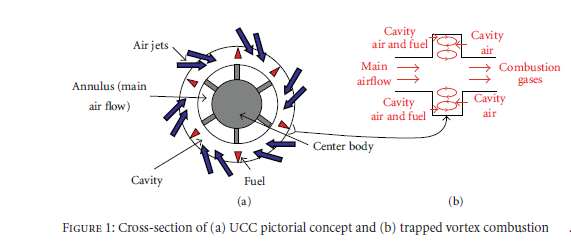
Поиск на нашем сайте Text 1 Flow Measurements Using Particle Image Velocimetry in The Ultracompact Combustor The potential for the ultracompact combustor (UCC) lie in future research to reduced fuel consumption and improved engine performance. The concept of an ultracompact combustor (UCC) has been in development for over ten years, offering the potential advantages of increasing gas turbine engine (GTE) performance while decreasing overall length and weight. Enabled by its short axial length, a UCC could be used in a GTE in place of the conventional main burner, as an interturbine burner, or both. Instead of using the axial length between the compressor and turbine, the UCC uses a channel around the engine’s circumference for the primary combustion zone (Figure 1). The combustion reaction is cavity-stabilized using trapped vortex combustion (TVC) along the outer wall of the circumferential flow path. By utilizing the circumference of the engine to complete the primary combustion, studies have shown the combustor section of a GTE could be shortened by 66% while maintaining 99% combustion efficiency. Specific thrust, a measure of thrust per unit air mass flow, of modern GTEs, is primarily limited by the maximum allowable turbine inlet temperature. As GTE main combustors operate lean overall, burning additional fuel will raise the turbine inlet temperature resulting in increased thermal energy which can then be extracted by the turbine to drive a larger fan or increase the exhaust velocity. An interturbine burner creates some of the same benefits of increasing turbine inlet temperature by burning additional fuel to reheat the flow after the high-pressure turbine has extracted much of the thermal energy. Currently, interturbine burners are limited to ground-based GTEs due to their size and weight. Developing the UCC for use in a gas turbine engine offers the potential benefits of lower engine weight, shorter length, higher specific thrust, and lower thrust-specific fuel consumption.
In order to develop the UCC concept into a working design suitable for use in a GTE, small-scale model representing a one sixth sector of the UCC was designed and built. The sector rig was built primarily to investigate the interaction between the primary (axial) and cavity (circumferential) flow paths and the radial vane cavity (RVC). The flow pattern is depicted schematically in Figure 1(a). Ideally, the hot low-density gaseous products of combustion would propagate inward, toward the main flow while the cooler higher-density reactants would tend to remain within the circumferential cavity. This flow pattern, which is generally consistent with a situation where buoyancy forces are dominant, would be advantageous in that residence times for the fuel-air mixture would be long, allowing for complete combustion. However, many questions remain about what type of mixing occurs at the interface between the cavity and the main flow (i.e., are the dominant forces buoyancy or baroclinicity?). If appreciable amounts of unburned fuel were to exit the cavity prematurely, engine efficiency would drop and any perceived advantage of the UCC design would be lost. The flow pattern near the interface of the circumferential cavity and the main flow is quite complex even for a nonreacting flow, let alone for a combustion environment where rotor blade passage induces unsteady flow. For example, Figure 1(b) depicts a possible vortex pattern normal to the circumferential flow direction in the cavity itself.
Vocabulary: Далее лексические упражнения: Exercises: 1. Find in the texts the English equivalents for the following expressions: (на русском) Analyze the function of participles in the following sentences and translate them into Russian. Text 2 Text 3 Text 4 Text 5 Text 6 Text 7 Text 1 Flow Measurements Using Particle Image Velocimetry in The Ultracompact Combustor The potential for the ultracompact combustor (UCC) lie in future research to reduced fuel consumption and improved engine performance. The concept of an ultracompact combustor (UCC) has been in development for over ten years, offering the potential advantages of increasing gas turbine engine (GTE) performance while decreasing overall length and weight. Enabled by its short axial length, a UCC could be used in a GTE in place of the conventional main burner, as an interturbine burner, or both. Instead of using the axial length between the compressor and turbine, the UCC uses a channel around the engine’s circumference for the primary combustion zone (Figure 1). The combustion reaction is cavity-stabilized using trapped vortex combustion (TVC) along the outer wall of the circumferential flow path. By utilizing the circumference of the engine to complete the primary combustion, studies have shown the combustor section of a GTE could be shortened by 66% while maintaining 99% combustion efficiency. Specific thrust, a measure of thrust per unit air mass flow, of modern GTEs, is primarily limited by the maximum allowable turbine inlet temperature. As GTE main combustors operate lean overall, burning additional fuel will raise the turbine inlet temperature resulting in increased thermal energy which can then be extracted by the turbine to drive a larger fan or increase the exhaust velocity. An interturbine burner creates some of the same benefits of increasing turbine inlet temperature by burning additional fuel to reheat the flow after the high-pressure turbine has extracted much of the thermal energy. Currently, interturbine burners are limited to ground-based GTEs due to their size and weight. Developing the UCC for use in a gas turbine engine offers the potential benefits of lower engine weight, shorter length, higher specific thrust, and lower thrust-specific fuel consumption.
In order to develop the UCC concept into a working design suitable for use in a GTE, small-scale model representing a one sixth sector of the UCC was designed and built. The sector rig was built primarily to investigate the interaction between the primary (axial) and cavity (circumferential) flow paths and the radial vane cavity (RVC). The flow pattern is depicted schematically in Figure 1(a). Ideally, the hot low-density gaseous products of combustion would propagate inward, toward the main flow while the cooler higher-density reactants would tend to remain within the circumferential cavity. This flow pattern, which is generally consistent with a situation where buoyancy forces are dominant, would be advantageous in that residence times for the fuel-air mixture would be long, allowing for complete combustion. However, many questions remain about what type of mixing occurs at the interface between the cavity and the main flow (i.e., are the dominant forces buoyancy or baroclinicity?). If appreciable amounts of unburned fuel were to exit the cavity prematurely, engine efficiency would drop and any perceived advantage of the UCC design would be lost. The flow pattern near the interface of the circumferential cavity and the main flow is quite complex even for a nonreacting flow, let alone for a combustion environment where rotor blade passage induces unsteady flow. For example, Figure 1(b) depicts a possible vortex pattern normal to the circumferential flow direction in the cavity itself.
Vocabulary: Далее лексические упражнения: Exercises: 1. Find in the texts the English equivalents for the following expressions: (на русском)
|
||
|
|
Последнее изменение этой страницы: 2019-04-30; просмотров: 274; Нарушение авторского права страницы; Мы поможем в написании вашей работы! infopedia.su Все материалы представленные на сайте исключительно с целью ознакомления читателями и не преследуют коммерческих целей или нарушение авторских прав. Обратная связь - 216.73.216.220 (0.007 с.) |