Заглавная страница Избранные статьи Случайная статья Познавательные статьи Новые добавления Обратная связь FAQ Написать работу КАТЕГОРИИ: ТОП 10 на сайте Приготовление дезинфицирующих растворов различной концентрацииТехника нижней прямой подачи мяча. Франко-прусская война (причины и последствия) Организация работы процедурного кабинета Смысловое и механическое запоминание, их место и роль в усвоении знаний Коммуникативные барьеры и пути их преодоления Обработка изделий медицинского назначения многократного применения Образцы текста публицистического стиля Четыре типа изменения баланса Задачи с ответами для Всероссийской олимпиады по праву 
Мы поможем в написании ваших работ! ЗНАЕТЕ ЛИ ВЫ?
Влияние общества на человека
Приготовление дезинфицирующих растворов различной концентрации Практические работы по географии для 6 класса Организация работы процедурного кабинета Изменения в неживой природе осенью Уборка процедурного кабинета Сольфеджио. Все правила по сольфеджио Балочные системы. Определение реакций опор и моментов защемления |
Study of transmission parameters of cable communication linesСодержание книги
Поиск на нашем сайте
PURPOSE OF WORK Learning primary and secondary transmission parameters of circuits, learning methods of parameters calculation and methods of cable transmission primary and secondary parameter measurement.
KEY positions A propagation of an electromagnetic field along a circuit is characterized by parameters which include: - the primary parameters: an active resistance of a circuit R, Ohm/km; an inductance of a circuit L, H/km; a capacitance of a circuit, F/km; a shunt conductance of a circuit G, S/km; - the secondary parameters: an attenuation factor a; dB/km; a phase factor b, radian; a surge impedance Zim, Ohm;a wavepropagation velocity V, m/s. An attenuation factor (|kilometric attenuation) of a circuit, a, |chn| is a parameter which characterizes|describe| power damping|reduc|capacity| of a signal, propagating along a line. Its|its| value|value| is equal to signal attenuation (in decibels) per circuit|chn| length|lenght| of 1 km. A phase factor|ratio| is determined by the alteration|variating| of signal phase (current or voltage one) when propagated along a line. The phase factor numerical value|importance||ratio| can be determined as a difference of signal phases (in radians|) for two points|dot-and-dash| of the circuit separated by |1 km distance. A surge impedance is resistance to a progressive voltage wave. For a uniform line, where indirect waves are absent, a surge impedance is the same in every point and it is equal to the ratio of voltage to current in any point of the circuit. A surge impedance is a complex quantity; its modulus is equal to a ratio of the voltage amplitude to the current one, and its argument is the voltage and the current phase difference in every point of the circuit. A propagation velocity (a phase velocity) V is a velocity of a monochromatic wave front propagation. It does not exceed the speed of light in free space (c = 3·108 mps). All of parameters of transmission have different values at different frequencies. The frequency dependence diagrams of primary and secondary transmission parameters of bilateral circuits are shown in Figure 2.1.
Among the primary parameters R and G onlycause loss of energy: R characterizesthermal loss in conductors and other metallic parts of cables such as shield, coverings, armor, C and G characterizeloss in conductor insulation. The values of primary transmission parameters can be obtained by the direct measurement, whereas the secondary parameters can be obtained by the indirect measurements only. While carrying out the measurements on a line, it is necessary to match an oscillator and load impedances with the impedance of line, therefore, as a rule; each measurement should be started with the line impedance determination. Using device МПП-300 the input parameters of the line can be measured by short-circuit and free-run methods (SCM, FRM) and therefore the secondary transmission parameters a, b, V, j and | Z im| are determined. In case high-frequency measurements for a long line its impendance can be measured as an input resistance of this line. An attenuation factor a can be also obtained by the method of level difference or comparison method (Fig. 2.2). A phase factor b can be measured by the method of indemnification in accordance with the chart of fig. 2.3. Voltages on the output of measured line and fading shop differ by a phase shift produced by the measured line, because the fading shop is constructed of active resistances and does not bring in the change of phases in the probed voltage. A phase difference between voltage on the output of line and the fading shop can equal zero only if length of a line equals zero or integer number of wave lengths measured frequency. Consequently, for every length of line there is a series of frequencies, for which a phase shift produced a line, is 2 p n. These frequencies are named critical. Knowing a length of line and a critical frequency, it is possible to define a phase factor for this frequency as
Figure 2.2 Measuring of fading: by the method of difference of levels and
Figure 2.3 Measuring phase factor by the method of indemnification
The secondary transmission parameter determination for the obtained results of the line input parameters measured in short-circuit and idling modes can be done according to the proper formulae using transmission equations for uniform lines ([1], p. 90):
here x is a distance between the beginning of the line and the point being observed; Ux, Ix are complex voltage and current at the x point; U0, I0 are complex voltage and current at the line’s beginning. Solving the equations given above with respect to U0 and I0 at x = l, we get
It follows from this that
here In case the receiver resistance is equal to zero (SCM,
In case the receiver resistance is infinite (IM,
Thus
An important point is that a short-circuit and an idling mode methods are used for short electric circuits only, where We designate phase shifts between a voltage and a current at the circuit’s beginning as j 0 and j ¥ (input impedance argument) for rear end short-circuit and idle running respectively. A value of input admittance
From Figure 2.3 it is obvious that
It should be noted that usually As j 0 and j ¥ are the arguments of entrance complex conductivities of Y0, Y ¥, arguments of entrance complex resistances of Z0, Z ¥will differ from them only by signs:
Therefore a modulus and an argument of the impedance in accordance with (2.3) will be
We designate
Where
With (2.1), (2.2) and (2.7) we get:
Using an identity
Hence determining real and imaginary parts, we can get the expressions for a and β:
Determination of the secondary transmission parameters using results of measurements of line input admittances Gвх 0, Gвх ∞ and input capacitances Cвх 0, Cвх ∞inshort-circuit and idling modes is recommended to perform in the sequence given below:
The calculated value of b can fall short of certified one at a rate frequency, because tg 2bL is a periodic function, and not only a single value of b but a range of them satisfies the equation (2.11)
here n is an integer. Therefore the task reduces to determination of p number multiple to be added to the obtained value. The number n is selected to approximate b to a tabular value. Having worked out the secondary transmission parameter values it is possible to calculate the primary ones. A propagation coefficient g is a complex number and can be represented as the following expression
A surge impedance
Multiplying g by Zsim we get the circuit impedance:
Dividing g by Zsim we get the circuit complex admittance:
Separating, the real and the imaginary parts of KEY QUESTIONS
3.1 The primary and secondary parameters of transmission, their units of measure, physical interpretation, frequency dependence. 3.2 What does methods of short-circuit and idling modes consist of for measurement of the secondary transmission parameters? 3.3 When is it possible to use methods of SCM and IM? 3.4 Sequence of circuit input admittance and capacitance measurement by МПП-300.
HOME work 4.1 Learn the following questions: – electric processes which take place in the balanced and coaxial cables; – frequency dependence of the primary and secondary transmission parameters; – methods of calculation of the primary and second transmission parameters; – methods of transmission parameter measurement. 4.2 Prepare the laboratory report and plan of work’s implementation according to the sections 5 and 9. 4.3 Prepare to the discussion of key questions. LABORATORY TASK 5.1 Acquaint yourself with equipment on-site and specify your implementation plan with a lecturer. 5.2 Cut the scheme for parameter measurement by the SCM and IM methods. 5.3 Measure cable input parameters in a short-circuit and an idling modes at the set frequencies. Note down the measured and the calculated values in a Table. 5.1. Table 5.1
EQIUPMENT 6.1 A model of cable line 0,5 km long, cable ПРППМ-1×2×1,2. 6.2 An input admittance bridge МПП-300. 6.3 A low-frequency generator ГЗ-56/1. 6.4 A selective level indicator ИУУ 5–300 kHz|. REPORT CONTENTS 7.1 Purpose of work. 7.2 Equipment. 7.3 Schemes and results of measurements, calculation results, frequency dependence diagrams of the primary and secondary transmission parameters, based on the measurement results. 7.4 Conclusions. LITERATURE 8.1 Гроднев И. И., Курбатов Н. Д. Линии связи. – М.: Связь, 1980. – С. 98–116, 120–133. 8.2 Гроднев И. И., Верник С. М. Линии связи. – М.: Радио и связь, 1988. – С. 120–131, 168–172. APPENDIX
|
||||||||||||||||||||||||||||||
|
|
Последнее изменение этой страницы: 2016-12-28; просмотров: 368; Нарушение авторского права страницы; Мы поможем в написании вашей работы! infopedia.su Все материалы представленные на сайте исключительно с целью ознакомления читателями и не преследуют коммерческих целей или нарушение авторских прав. Обратная связь - 3.21.205.188 (0.01 с.) |


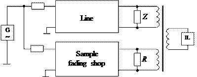
 , here L - length of the probed line. A critical frequency is determined by an indicator (IL, indicator of level) which will show minimum at the counter-opposite connection of coils of differential transformer (DT).

 is a propagation constant;

 is a load resistance (of receiver).
 ) the input resistance
 (2.1)
(2.1) ),
), (2.2)
(2.2) (2.3)
(2.3) dB. For long lines
  dB; in this case
  and
and  Also for lines with attenuation coefficient lying in the range of 4,6…13 dB SCM and IM methods are not used because attenuation coefficient is determinated with low accuracy.
 for SCM and IM can be determined from vector diagrams (Figure 2.3).

 (2.4)
(2.4)
 (2.5)
(2.5) has a negative value (a sign
  – positive (a sign is "plus").


 (2.6)
(2.6) (2.7)
(2.7) ,
,  (2.8)
(2.8) (2.9)
(2.9) we can write:
 (2.10)
 (2.11)
 (2.12)
 (2.14)
 (2.16)
 (2.18)
 (2.20)
 (2.22)
 (2.13)
 (2.15)
 (2.17)
 (2.19)
 (2.21)


 .
. . (2.23)
 . (2.24)
 and
and  and dividing the imaginary components by w we get the primary parameters of transmission R, L, C, G.