Заглавная страница Избранные статьи Случайная статья Познавательные статьи Новые добавления Обратная связь FAQ Написать работу КАТЕГОРИИ: ТОП 10 на сайте Приготовление дезинфицирующих растворов различной концентрацииТехника нижней прямой подачи мяча. Франко-прусская война (причины и последствия) Организация работы процедурного кабинета Смысловое и механическое запоминание, их место и роль в усвоении знаний Коммуникативные барьеры и пути их преодоления Обработка изделий медицинского назначения многократного применения Образцы текста публицистического стиля Четыре типа изменения баланса Задачи с ответами для Всероссийской олимпиады по праву 
Мы поможем в написании ваших работ! ЗНАЕТЕ ЛИ ВЫ?
Влияние общества на человека
Приготовление дезинфицирующих растворов различной концентрации Практические работы по географии для 6 класса Организация работы процедурного кабинета Изменения в неживой природе осенью Уборка процедурного кабинета Сольфеджио. Все правила по сольфеджио Балочные системы. Определение реакций опор и моментов защемления |
Comparison with other drive mechanismsСодержание книги
Поиск на нашем сайте
The definite velocity ratio which results from having teeth gives gears an advantage over other drives (such as traction drives and V-belts) in precision machines such as watches that depend upon an exact velocity ratio. In cases where driver and follower are in close proximity gears also have an advantage over other drives in the reduced number of parts required; the downside is that gears are more expensive to manufacture and their lubrication requirements may impose a higher operating cost. The automobile transmission allows selection between gears to give various mechanical advantages. Gear types External vs. internal gears
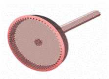
Unlike most gears, an internal gear (shown here) does not cause direction reversal. An external gear is one with the teeth formed on the outer surface of a cylinder or cone. Conversely, an internal gear is one with the teeth formed on the inner surface of a cylinder or cone. For bevel gears, an internal gear is one with the pitch angle exceeding 90 degrees. Spur gears Spur gears are the simplest and most common type of gear. Their general form is a cylinder or disk. The teeth project radially, and with these " straight-cut gears ", the leading edges of the teeth are aligned parallel to the axis of rotation. These gears can only mesh correctly if they are fitted to parallel axles. Helical gears
Helical gears from a Meccano construction set. Helical gears offer a refinement over spur gears. The leading edges of the teeth are not parallel to the axis of rotation, but are set at an angle. Since the gear is curved, this angling causes the tooth shape to be a segment of a helix. The angled teeth engage more gradually than do spur gear teeth. This causes helical gears to run more smoothly and quietly than spur gears. Helical gears also offer the possibility of using non-parallel shafts. A pair of helical gears can be meshed in two ways: with shafts oriented at either the sum or the difference of the helix angles of the gears. These configurations are referred to as parallel or crossed, respectively. The parallel configuration is the more mechanically sound. In it, the helices of a pair of meshing teeth meet at a common tangent, and the contact between the tooth surfaces will, generally, be a curve extending some distance across their face widths. In the crossed configuration, the helices do not meet tangentially, and only point contact is achieved between tooth surfaces. Because of the small area of contact, crossed helical gears can only be used with light loads. Quite commonly, helical gears come in pairs where the helix angle of one is the negative of the helix angle of the other; such a pair might also be referred to as having a right-handed helix and a left-handed helix of equal angles. If such a pair is meshed in the 'parallel' mode, the two equal but opposite angles add to zero: the angle between shafts is zero -- that is, the shafts are parallel. If the pair is meshed in the 'crossed' mode, the angle between shafts will be twice the absolute value of either helix angle. Note that 'parallel' helical gears need not have parallel shafts -- this only occurs if their helix angles are equal but opposite. The 'parallel' in 'parallel helical gears' must refer, if anything, to the (quasi) parallelism of the teeth, not to the shaft orientation. As mentioned at the start of this section, helical gears operate more smoothly than do spur gears. With parallel helical gears, each pair of teeth first make contact at a single point at one side of the gear wheel; a moving curve of contact then grows gradually across the tooth face. It may span the entire width of the tooth for a time. Finally, it recedes until the teeth break contact at a single point on the opposite side of the wheel. Thus force is taken up and released gradually. With spur gears, the situation is quite different. When a pair of teeth meet, they immediately make line contact across their entire width. This causes impact stress and noise. Spur gears make a characteristic whine at high speeds and can not take as much torque as helical gears because their teeth are receiving impact blows. Whereas spur gears are used for low speed applications and those situations where noise control is not a problem, the use of helical gears is indicated when the application involves high speeds, large power transmission, or where noise abatement is important. The speed is considered to be high when the pitch line velocity (that is, the circumferential velocity) exceeds 5000 ft/minA disadvantage of helical gears is a resultant thrust along the axis of the gear, which needs to be accommodated by appropriate thrust bearings, and a greater degree of sliding friction between the meshing teeth, often addressed with specific additives in the lubricant. Double helical gears Double helical gears, also known as herringbone gears, overcome the problem of axial thrust presented by 'single' helical gears by having teeth that set in a 'V' shape. Each gear in a double helical gear can be thought of as two standard, but mirror image, helical gears stacked. This cancels out the thrust since each half of the gear thrusts in the opposite direction. They can be directly interchanged with spur gears without any need for different bearings. Where the oppositely angled teeth meet in the middle of a herringbone gear, the alignment may be such that tooth tip meets tooth tip, or the alignment may be staggered, so that tooth tip meets tooth trough. The latter type of alignment results in what is known as a Wuest type herringbone gear. With the older method of fabrication, herringbone gears had a central channel separating the two oppositely-angled courses of teeth. This was necessary to permit the shaving tool to run out of the groove. The development of the Sykes gear shaper now makes it possible to have continuous teeth, with no central gap. Bevel gears
Bevel gear used to lift floodgate by means of central screw. Bevel gears are essentially conically shaped, although the actual gear does not extend all the way to the vertex (tip) of the cone that bounds it. With two bevel gears in mesh, the vertices of their two cones lie on a single point, and the shaft axes also intersect at that point. The angle between the shafts can be anything except zero or 180 degrees. Bevel gears with equal numbers of teeth and shaft axes at 90 degrees are called miter gears. The teeth of a bevel gear may be straight-cut as with spur gears, or they may be cut in a variety of other shapes. ' Spiral bevel gears' have teeth that are both curved along their (the tooth's) length; and set at an angle, analogously to the way helical gear teeth are set at an angle compared to spur gear teeth. ' Zero bevel gears' have teeth which are curved along their length, but not angled. Spiral bevel gears have the same advantages and disadvantages relative to their straight-cut cousins as helical gears do to spur gears. Straight bevel gears are generally used only at speeds below 5 m/s (1000 ft/min), or, for small gears, 1000 r.p.m. Crown gear
A crown gear A crown gear or contrate gear is a particular form of bevel gear whose teeth project at right angles to the plane of the wheel; in their orientation the teeth resemble the points on a crown. A crown gear can only mesh accurately with another bevel gear, although crown gears are sometimes seen meshing with spur gears. A crown gear is also sometimes meshed with an escapement such as found in mechanical clocks. Hypoid gears Hypoid gears resemble spiral bevel gears, except that the shaft axes are offset, not intersecting. The pitch surfaces appear conical but, to compensate for the offset shaft, are in fact hyperboloids of revolution. Hypoid gears are almost always designed to operate with shafts at 90 degrees. Depending on which side the shaft is offset to, relative to the angling of the teeth, contact between hypoid gear teeth may be even smoother and more gradual than with spiral bevel gear teeth. Also, the pinion can be designed with fewer teeth than a spiral bevel pinion, with the result that gear ratios of 60:1 and higher are "entirely feasible" using a single set of hypoid gears. Worm gear
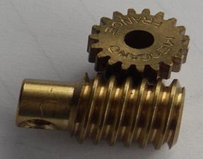
A worm and gear from a Meccano construction set A worm is a gear that resembles a screw. It is a species of helical gear, but its helix angle is usually somewhat large(ie., somewhat close to 90 degrees) and its body is usually fairly long in the axial direction; and it is these attributes which give it its screw like qualities. A worm is usually meshed with an ordinary looking, disk-shaped gear, which is called the "gear", the "wheel", the "worm gear", or the "worm wheel". The prime feature of a worm-and-gear set is that it allows the attainment of a high gear ratio with few parts, in a small space. Helical gears are, in practice, limited to gear ratios of 10:1 and under; worm gear sets commonly have gear ratios between 10:1 and 100:1, and occasionally 500:1. In worm-and-gear sets, where the worm's helix angle is large, the sliding action between teeth can be considerable, and the resulting frictional loss causes the efficiency of the drive to be usually less than 90 percent, sometimes less than 50 percent, which is far less than other types of gears. The distinction between a worm and a helical gear is made when at least one tooth persists for a full 360 degree turn around the helix. If this occurs, it is a 'worm'; if not, it is a 'helical gear'. A worm may have as few as one tooth. If that tooth persists for several turns around the helix, the worm will appear, superficially, to have more than one tooth, but what one in fact sees is the same tooth reappearing at intervals along the length of the worm. The usual screw nomenclature applies: a one-toothed worm is called "single thread" or "single start"; a worm with more than one tooth is called "multiple thread" or "multiple start". We should note that the helix angle of a worm is not usually specified. Instead, the lead angle, which is equal to 90 degrees minus the helix angle, is given. In a worm-and-gear set, the worm can always drive the gear. However, if the gear attempts to drive the worm, it may or may not succeed. Particularly if the lead angle is small, the gear's teeth may simply lock against the worm's teeth, because the force component circumferential to the worm is not sufficient to overcome friction. Whether this will happen depends on a function of several parameters; however, an approximate rule is that if the tangent of the lead angle is greater than the coefficient of friction, the gear will not lock. Worm-and-gear sets that do lock in the above manner are called "self locking". The self locking feature can be an advantage, as for instance when it is desired to set the position of a mechanism by turning the worm and then have the mechanism hold that position. An example of this is the tuning mechanism on some types of stringed instruments.
Helical and Worm Hand, ANSI/AGMA 1012-G05 If the gear in a worm-and-gear set is an ordinary helical gear only point contact between teeth will be achieved. If medium to high power transmission is desired, the tooth shape of the gear is modified to achieve more intimate contact with the worm thread. A noticeable feature of most such gears is that the tooth tops are concave, so that the gear partly envelopes the worm. A further development is to make the worm concave (viewed from the side, perpendicular to its axis) so that it partly envelopes the gear as well; this is called a cone-drive or Hindley worm. A right hand helical gear or right hand worm is one in which the teeth twist clockwise as they recede from an observer looking along the axis. The designations, right hand and left hand, are the same as in the long established practice for screw threads, both external and internal. Two external helical gears operating on parallel axes must be of opposite hand. An internal helical gear and its pinion must be of the same hand.It is used to get high velocity ratio. A left hand helical gear or left hand worm is one in which the teeth twist counterclockwise as they recede from an observer looking along the axis.
Rack and pinion
Rack and pinion animation A rack is a toothed bar or rod that can be thought of as a sector gear with an infinitely large radius of curvature. Torque can be converted to linear force by meshing a rack with a pinion: the pinion turns; the rack moves in a straight line. Such a mechanism is used in automobiles to convert the rotation of the steering wheel into the left-to-right motion of the tie rod(s). Racks also feature in the theory of gear geometry, where, for instance, the tooth shape of an interchangeable set of gears may be specified for the rack (infinite radius), and the tooth shapes for gears of particular actual radii then derived from that. The rack and pinion gear type is employed in a rack railway. Epicyclic gearing In an ordinary gear train, the gears rotate but their axes are stationary. An epicyclic gear train is one in which one or more of the axes also moves. Examples are the sun and planet gear system invented by the company of James Watt, in which the axis of the planet gear revolves around the central sun gear; and the differential gear system used to drive the wheels of automobiles, in which the axis of the central bevel pinion is turned "end over end" by the ring gear, the drive to the wheels being taken off by bevel gears meshing with the central bevel pinion. With the differential gearing, the sum of the two wheel speeds is fixed, but how it is divided between the two wheels is undetermined, so the outer wheel can run faster and the inner wheel slower on corners.
Unit 8 Bearings. І. Language Ex.1. Remember the following words and word combinations:
|
|||||||
|
|
Последнее изменение этой страницы: 2016-09-19; просмотров: 359; Нарушение авторского права страницы; Мы поможем в написании вашей работы! infopedia.su Все материалы представленные на сайте исключительно с целью ознакомления читателями и не преследуют коммерческих целей или нарушение авторских прав. Обратная связь - 3.145.103.119 (0.01 с.) |