Заглавная страница Избранные статьи Случайная статья Познавательные статьи Новые добавления Обратная связь КАТЕГОРИИ: ТОП 10 на сайте Приготовление дезинфицирующих растворов различной концентрацииТехника нижней прямой подачи мяча. Франко-прусская война (причины и последствия) Организация работы процедурного кабинета Смысловое и механическое запоминание, их место и роль в усвоении знаний Коммуникативные барьеры и пути их преодоления Обработка изделий медицинского назначения многократного применения Образцы текста публицистического стиля Четыре типа изменения баланса Задачи с ответами для Всероссийской олимпиады по праву 
Мы поможем в написании ваших работ! ЗНАЕТЕ ЛИ ВЫ?
Влияние общества на человека
Приготовление дезинфицирующих растворов различной концентрации Практические работы по географии для 6 класса Организация работы процедурного кабинета Изменения в неживой природе осенью Уборка процедурного кабинета Сольфеджио. Все правила по сольфеджио Балочные системы. Определение реакций опор и моментов защемления |
Potential distribution along the nonuniform circuit unit
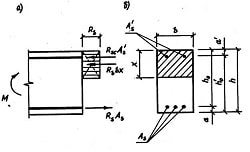
The nonuniform subcircuit terms the part of an electric circuit containing a source of the EMF. We will consider distribution of a potential on different circuit units with extraneous forces. At first we will consider a nonuniform electric circuit unit 1-2 consisting only one source of the EMF (see Fig. 13). In open-circuit (idle) mode the current through a source does not flow I =0, then all work of extraneous force A EXTR is used only for separation of charges in a source, that is to say for creation of EMF. Thus an open-circuit voltage on the source equals to greatest possible potential difference on source terminals 1-2 (dashed line on fig. 13):
Thus, the EMF of a source e is a greatest possible voltage on its terminals at no-load condition, and numerically is equal to a work done by extraneous forces during a transition of electric charge unit through the source. The EMF of a source is measured in volts. When through a source e the current I ¹ 0 flows, then part of work A EXTR of extraneous forces will be used for overcoming of internal resistance of the source r. As a result, the source heats up. This part of work according to Joule-Lentz law is equal: ARES=I 2 r D t=q×Ir. Then voltage on the source terminals 1-2 will be less, than in idle mode conditions (53) on value of voltage drop Ir on internal resistance of the source:
On a Fig. 13 this voltage drop Ir on internal resistance of the source r is denoted by an arrow downwards.
Let's consider a nonuniform circuit unit 1-3, which contains the source e and an external (load) resistor R (see Fig. 14). Then part of work A EXTR of extraneous forces will be used for overcoming of internal resistance of the source r and resistance of load resistor R. As a result, the source and the external resistor heat up. Therefore, this part of work we can obtain using a Joule-Lentz law: ARES=I 2(r+R)D t=q×I (r+R). Then voltage on circuit unit terminals 1-3 in comparison with 1-2 (54) is being decreased by value ofvoltage drop Ir, and, in addition, by value of voltage drop IR on external resistor R:
On a Fig. 14 both voltage drops Ir on internal resistance of the source r and on load resistor R are denoted by arrows downwards.
Let's consider a circuit unit 1-4, which contains the source e1, which action of an extraneous forces coincides with a current direction, external resistance R, and a source e2, which action of an extraneous forces does not coincide with a current direction (see Fig. 15). In case e2<e1, it means, that the source e2 will be charged by a current, created by the source e1. Then part of work A EXTR of extraneous forces will be used for overcoming of internal resistance of the source r 1, for overcoming of resistance of load resistor R, for overcoming of internal resistance of the second source r 2: ARES=I 2(r 1 +R + r 2)D t=q×I (r 1 +R + r 2), and, in addition, for source e2 charging: A CH = e2 q. Therefore voltage on circuit unit terminals 1-4 in comparison with 1-3 (55) is being decreased by value ofvoltage drop Ir 2on internal resistance of second source, and in addition by value of it EMFe2:
As we can see, e1 is positive, because direction of extraneous forces work (from “–“ to “+” inside the source) coincides with direction of current I, but e2 is negative, because direction of extraneous forces work noncoincides with direction of current I.
If terminals 1 and 3 of nonuniform circuit unit 1-3 that is shown on Fig, 14 are closed by a conductor, then potentials of points 1 and 3 will be equalized: j1=j3,
and we obtain the elementary variant of closed electric circuit (see Fig. 16). In this case all work A EXTR=e q of extraneous forces will be used for overcoming of internal resistance of the source r and resistance of load resistor R: AEXTR = A RES= q×I (r+R). From (55) we obtain, then all EMF of the source e drops on internal resistance of the source r and on external resistor R:
From formulas (53) - (56) we can see, that according to definition the voltage U –is a potential difference on terminals of a circuit unit. However, it is necessary to note, that voltage Ur on terminals of an EMF source (54) is being accepted with plus sign, and is being defined as work of extraneous (internal) forces on transition of a unit positive charge. Thus, from a Fig.14 we can see, that it is equal Ur= j2–j1 to a difference of a terminating potential j2 (greater), and an initial potential j1 (smaller). Voltage on any nonuniform circuit unit (53) - (56) is being analogously defined. If we define a voltage UR on terminals of the homogeneous circuit unit 2-3, which is not containing an EMF source (Fig. 14), it will be positive, when we consider it as a work of field forces (external) on transition of a unit positive charge. Thus, from a Fig. 14 we can see, that it is equal UR= j2–j3 to a difference of an initial potential (greater) j2, and a terminating potential (smaller) j3:
Therefore for the homogeneous circuit unit AB from fig. 10 Ohm's law write down in the form of the formula (20).
|
|||||||||
|
|
Последнее изменение этой страницы: 2016-04-26; просмотров: 58; Нарушение авторского права страницы; Мы поможем в написании вашей работы! infopedia.su Все материалы представленные на сайте исключительно с целью ознакомления читателями и не преследуют коммерческих целей или нарушение авторских прав. Обратная связь - 18.223.28.70 (0.006 с.) |
 Fig. 13 – Potential distribution on terminals of a sourse of the EMF
 ; [e]= V, (53)
 . (54)
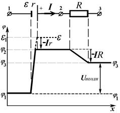 Fig. 14 – Potential distribution along a nonuniform circuit unit
 . (55)
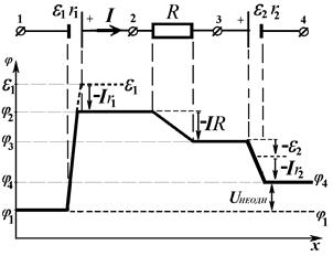 Fig. 15 – Potential distribution along a nonuniform circuit unit, which contain opposite connection of EMF
 . (56)
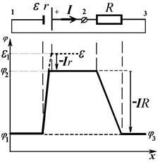 Рис. 16 – Potential distribution along a closed circuit
 . (57)
 . (58)