Заглавная страница Избранные статьи Случайная статья Познавательные статьи Новые добавления Обратная связь КАТЕГОРИИ: ТОП 10 на сайте Приготовление дезинфицирующих растворов различной концентрацииТехника нижней прямой подачи мяча. Франко-прусская война (причины и последствия) Организация работы процедурного кабинета Смысловое и механическое запоминание, их место и роль в усвоении знаний Коммуникативные барьеры и пути их преодоления Обработка изделий медицинского назначения многократного применения Образцы текста публицистического стиля Четыре типа изменения баланса Задачи с ответами для Всероссийской олимпиады по праву 
Мы поможем в написании ваших работ! ЗНАЕТЕ ЛИ ВЫ?
Влияние общества на человека
Приготовление дезинфицирующих растворов различной концентрации Практические работы по географии для 6 класса Организация работы процедурного кабинета Изменения в неживой природе осенью Уборка процедурного кабинета Сольфеджио. Все правила по сольфеджио Балочные системы. Определение реакций опор и моментов защемления |
Special Tools - Grip: 57001-1591
Rotor Holder: 57001-1658 Torque - Alternator Rotor Bolt: 155 N·m (15.8 kgf·m, 114 ft·lb)
• Install the torque limiter [B] and starter idle gear [C]. • Install the alternator cover (see Alternator Cover Installa- tion).
Alternator Inspection There are three types of alternator failures: short, open (wire burned out), or loss in rotor magnetism. A short or open in one of the coil wires will result in either a low output, or no output at all. A loss in rotor magnetism, which may be caused by dropping or hitting the alternator, by leaving it near an electromagnetic field, or just by aging, will result in low output.
○Turn off the ignition switch. ○Disconnect the alternator lead connector [A]. ○Connect the hand tester as shown in the table 1. ○Start the engine. ○Run it at the rpm given in the table 1. ○Note the voltage readings (total 3 measurements). Table 1 Alternator Output Voltage
• Check the stator coil resistance as follows. ○Stop the engine. ○Connect the hand tester as shown in the table 2. ○Note the readings (total 3 measurement). Table 2 Stator Coil Resistance
• Using the highest resistance range of the hand tester, measure the resistance between each of the black leads and chassis ground.
Special Tool - Hand Tester: 57001-1394
EX650A Models • Remove: Bolts [A]
• Remove the regulator/rectifier [B].
• Remove the bolts [A]. • Disconnect the connector [B]. • Remove the regulator/rectifier [C].
• Check conductivity of the following pair of terminals. Rectifier Circuit Inspection
NOTE ○The actual meter reading varies with the meter used and the individual rectifier, but, generally speaking the lower reading should be from zero to one half the scale. Regulator Circuit Check
To test the regulator out of circuit, use three 12 V batteries and a test light (12 V 3 ~ 6 W bulb in a socket with leads).
• Check to be sure the rectifier circuit is normal before con- tinuing.
○Connect the test light and the 12 V battery to the regula- tor/rectifier as shown. ○Check the BK1, BK2 and BK3 terminal respectively.
Replace it.
○Connect the test light and the 12 V battery in the same manner as specified in the “Regulator Circuit Test-1st Step”. ○Apply 12 V to the voltage BR terminal. ○Check the BK1, BK2 and BK3 terminal respectively.
Replace it.
○Connect the test light and the 12 V battery in the same manner as specified in the “Regulator Circuit Test-1st Step”. ○Momentarily apply 24 V to the voltage BR terminal by adding a 12 V battery. ○Check the BK1, BK2 and BK3 terminals respectively.
• Check the battery condition (see Charging Condition In- spection). • Warm up the engine to obtain actual alternator operating conditions. • Remove the seat (see Seat Removal in the Frame chap- ter). • Check that the ignition switch is turned off, and connect the hand tester [A] to the battery terminals [B].
|
||||||||||||||||||||||||||||||||||
|
|
Последнее изменение этой страницы: 2016-08-10; просмотров: 318; Нарушение авторского права страницы; Мы поможем в написании вашей работы! infopedia.su Все материалы представленные на сайте исключительно с целью ознакомления читателями и не преследуют коммерческих целей или нарушение авторских прав. Обратная связь - 3.12.108.236 (0.009 с.) |
 • Apply a thin coat of molybdenum disulfide grease to the shafts [A], and install them.
 • To check the alternator output voltage, do the following procedures.
 If the output voltage shows the value in the table, the al- ternator operates properly.
 Regulator/Rectifier Inspection
 • Disconnect the connector [A].
 EX650B Models
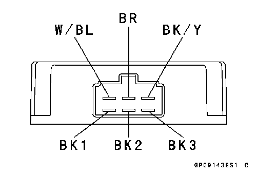 Rectifier Circuit Check
 • Do the 1st step regulator circuit test.
 • Do the 2nd step regulator circuit test.
 • Do the 3rd step regulator circuit test.
 Charging Voltage Inspection