Заглавная страница Избранные статьи Случайная статья Познавательные статьи Новые добавления Обратная связь КАТЕГОРИИ: ТОП 10 на сайте Приготовление дезинфицирующих растворов различной концентрацииТехника нижней прямой подачи мяча. Франко-прусская война (причины и последствия) Организация работы процедурного кабинета Смысловое и механическое запоминание, их место и роль в усвоении знаний Коммуникативные барьеры и пути их преодоления Обработка изделий медицинского назначения многократного применения Образцы текста публицистического стиля Четыре типа изменения баланса Задачи с ответами для Всероссийской олимпиады по праву 
Мы поможем в написании ваших работ! ЗНАЕТЕ ЛИ ВЫ?
Влияние общества на человека
Приготовление дезинфицирующих растворов различной концентрации Практические работы по географии для 6 класса Организация работы процедурного кабинета Изменения в неживой природе осенью Уборка процедурного кабинета Сольфеджио. Все правила по сольфеджио Балочные системы. Определение реакций опор и моментов защемления |
Bearing Driver Set: 57001-1129
Drive Chain Slack Inspection • Refer to the Drive Chain Slack Inspection in the Periodic Maintenance chapter. Drive Chain Slack Adjustment • Refer to the Drive Chain Slack Adjustment in the Periodic Maintenance chapter. Wheel Alignment Inspection/Adjustment • Refer to the Wheel Alignment Inspection in the Periodic Maintenance chapter. Drive Chain Wear Inspection • Refer to the Drive Chain Wear Inspection in the Periodic Maintenance chapter. Drive Chain Lubrication • Refer to the Drive Chain Lubrication Condition Inspection in the Periodic Maintenance chapter. Drive Chain Removal NOTE ○Since the drive chain is installed through the swingarm, the chain cannot be removed other than by cutting it. Prepare the new link pin, link plate, grease seals, and tools for rejoining the chain. • Using a suitable tool, cut the drive chain by removing the link pins. Recommended Tool: EK Joint Tool #50
Body [A] Handlebar [B]
For Riveting [E] Plate Holder (a) [F] Plate Holder (b) [G] Gauge [H]
• Set the cutting and riveting pin [B] as shown.
• Screw the pin holder until it touches chain pin.
• Turn the pin holder with wrench [B] clockwise to extract chain pin.
• Engage the new drive chain to the old drive chain and pull the end of the old drive chain until they are changing the position. • Remove the old drive chain from the new drive chain. • Apply grease to the link pins [A] and grease seals [B] [C]. • Engage the drive chain on the rear sprocket through the swingarm. • Insert the link pins in the drive chain ends. • Install the grease seals [C]. • Install the link plate so that the mark [D] faces out. • Push the link plate by hand or plier to fix it. • In case of grease seal chain, be sure to set the grease seals correctly.
• Turn the pin holder by hand until plate holder (b) touches the other link plate.
• Take off the plate holder (a).
• Rivet it. • Same work for the other link pin.
• Measure the outside diameter [A] of the link pin and link plates width [B]. Link Pin Outside Diameter Standard: 5.7 ~ 6.0 mm (0.22 ~ 0.24 in.) Link Plates Outside Width Standard: 17.25 ~ 17.45 mm (0.679 ~ 0.687 in.)
• Check: Movement of the Rollers • Adjust the drive chain slack after installing the chain (see Drive Chain Slack Adjustment in the Periodic Mainte- nance chapter).
Engine Sprocket Removal
Engine Sprocket Cover Bolts [A] Engine Sprocket Cover [B]
Speed Sensor Bracket Bolts [A] Speed Sensor Bracket [B]
• Remove the engine sprocket nut [B] and washer. NOTE ○When loosening the engine sprocket nut, hold the rear brake on.
• Remove the axle cotter pin, and loosen the rear axle nut.
• Loosen the drive chain (see Drive Chain Slack Adjust- ment in the Periodic Maintenance chapter). • Remove the drive chain from the rear sprocket toward the right. • Pull the engine sprocket [A] with drive chain [B] off the output shaft [C]. • Disengage the drive chain from the engine sprocket.
Engine Sprocket Installation
• Install the engine sprocket [A] so that “OUTSIDE” letters face outward. • Apply molybdenum disulfide oil solution to the threads of the output shaft and seating surface of the engine sprocket nut. • After torquing the engine sprocket nut, bend the one side of the washer [B] over the nut. NOTE ○Tighten the engine sprocket nut while applying the rear brake. • Tighten: Torque - Engine Sprocket Nut: 125 N·m (12.7 kgf·m, 92 ft·lb) Speed Sensor Bracket Bolts: 9.8 N·m (1.0 kgf·m, 87 in·lb) • Install the engine sprocket cover, and tighten the bolts. • Adjust the drive chain slack after installing the sprocket (see Drive Chain Slack Adjustment in the Periodic Main- tenance chapter). • Bend the end of axle cotter pin surely after tightening the axle nut (see Rear Wheel Installation in the Wheels/Tires chapter).
• Remove the rear wheel (see Rear Wheel Removal in the Wheels/Tires chapter). • Remove the rear sprocket nuts [A]. • Remove the rear sprocket [B].
• Install the sprocket facing the tooth number marking [A] outward. • Tighten the rear sprocket nuts. Torque - Rear Sprocket Nuts: 59 N·m (6.0 kgf·m, 44 ft·lb) • Install the rear wheel (see Rear Wheel Installation in the Wheels/Tires chapter).
• Apply high-temperature grease to the coupling grease seal lips [A]. • Apply grease to the coupling internal surface [B].
O-ring [B] • Install the collar [C].
• Remove: Coupling Grease Seal Circlip [A]
|
|||||||||
|
|
Последнее изменение этой страницы: 2016-08-10; просмотров: 280; Нарушение авторского права страницы; Мы поможем в написании вашей работы! infopedia.su Все материалы представленные на сайте исключительно с целью ознакомления читателями и не преследуют коммерческих целей или нарушение авторских прав. Обратная связь - 3.144.84.155 (0.016 с.) |
 Cutting and Riveting Pin [C] For Cutting [D]
 • Grind [A] the pin head to make it flat.
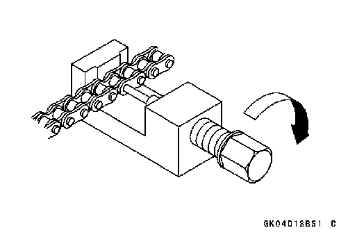 • Be sure that the cutting pin hits center of chain pin.
 • Screw the handlebar [A] into body.
 Drive Chain Installation
 • Set the plate holder (a) [A] and plate holder (b) [B] on the body.
 • Fit the plate holder (a) to link plate.
 • Turn the pin holder by wrench clockwise until two pins of link come into groove of plate holder (a).
 • Set the plate holder (b) [A] and cutting and riveting pin [B] as shown.
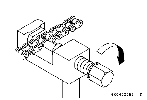 • Turn the pin holder until riveting pin touches link pin.
 • Turn the wrench clockwise until tip of riveting pin hits of link pin.
 • After staking, check the staked area of the link pin for cracks.
 If the reading exceeds the specified length, cut and rejoin the chain again.
 • Remove:
 • Remove:
 • Flatten out the bended washer [A].
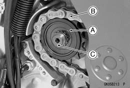 • Raise the rear wheel off the ground with stand.
 • Replace the sprocket washer and axle cotter pin.
 Rear Sprocket Removal
 Rear Sprocket Installation
 Coupling Installation
 • Grease the following. Wheel Flange Portion [A]
 Coupling Bearing Removal