Заглавная страница Избранные статьи Случайная статья Познавательные статьи Новые добавления Обратная связь КАТЕГОРИИ: ТОП 10 на сайте Приготовление дезинфицирующих растворов различной концентрацииТехника нижней прямой подачи мяча. Франко-прусская война (причины и последствия) Организация работы процедурного кабинета Смысловое и механическое запоминание, их место и роль в усвоении знаний Коммуникативные барьеры и пути их преодоления Обработка изделий медицинского назначения многократного применения Образцы текста публицистического стиля Четыре типа изменения баланса Задачи с ответами для Всероссийской олимпиады по праву 
Мы поможем в написании ваших работ! ЗНАЕТЕ ЛИ ВЫ?
Влияние общества на человека
Приготовление дезинфицирующих растворов различной концентрации Практические работы по географии для 6 класса Организация работы процедурного кабинета Изменения в неживой природе осенью Уборка процедурного кабинета Сольфеджио. Все правила по сольфеджио Балочные системы. Определение реакций опор и моментов защемления |
Kawasaki Bond (Silicone Sealant): 92104-0004
Clutch Lever Free Play Inspection • Refer to the Clutch Operation Inspection in the Periodic Maintenance chapter. Clutch Lever Free Play Adjustment • Refer to the Clutch Operation Inspection in the Periodic Maintenance chapter.
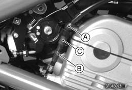
• Remove: Right Frame Cover (see Frame Cover Removal in the Frame chapter) Right Center Fairing (see Center Fairing Removal in the Frame chapter) • Slide the dust cover [A] at the middle of clutch cable out of place. • Loosen the locknut [B], and turn the adjusting nut [C] to give the cable plenty of play.
• Line up the slots [A] in the clutch lever and adjuster [B], and then free the cable from the lever. • Free the clutch inner cable tip from the clutch release lever.
• Pull the clutch cable out of the frame.
Clutch Cable Installation • Run the clutch cable correctly (see Cable, Wire, and Hose Routing section in the Appendix chapter). • Adjust the clutch cable (see Clutch Operation Inspection in the Periodic Maintenance chapter). Clutch Cable Lubrication • Refer to the Chassis Parts Lubrication in the Periodic Maintenance chapter.
Clutch Lever Installation
• Tighten the upper clamp bolt first, and then the lower clamp bolt. There will be a gap at the lower part of the clamp after tightening. Torque - Clutch Lever Clamp Bolts: 7.8 N·m (0.80 kgf·m, 69 in·lb)
The adjuster has 5 positions so that the clutch lever posi- tion can be adjusted to suit the operator’s hand. • Push the lever forward and turn the adjuster [A] to align the number with the arrow mark [B] on the lever holder. ○The distance from the grip to the lever is minimum at num- ber 5 and maximum at number 1.
Clutch Cover Removal
Engine Oil (Drain, see Engine Oil Change in the Periodic Maintenance chapter) Right Frame Cover (see Frame Cover Removal in the Frame chapter) Right Center Fairing (see Center Fairing Removal in the Frame chapter) Clutch Cable Lower End [A] Clutch Cover Mounting Bolts [B]
About 90° [C] • Push the release lever toward the front of the motorcycle and tape the release lever to the clutch cover to prevent the release shaft from falling out.
Clutch Cover Installation • Apply silicone sealant to the area [A] where the mating surface of the crankcase touches the clutch cover gasket and to the crankshaft sensor lead grommet [B]. Sealant - Kawasaki Bond (Silicone Sealant): 92104-0004 • Be sure that the dowel pins [C] are in position. • Replace the clutch cover gasket [D] with a new one. • Tighten the clutch cover mounting bolts. Torque - Clutch Cover Mounting Bolts: 9.8 N·m (1.0 kgf·m, 87 in·lb)
Release Shaft Removal
• Remove the clutch cover (see Clutch Cover Removal). • Pull the lever and shaft assembly straight out of the clutch cover.
• Apply high-temperature grease to the oil seal lips on the upper ridge of the clutch cover. • Apply engine oil to the needle bearings in the hole of the clutch cover. • Apply molybdenum disulfide grease to the pusher-holding portion [A] on the release shaft. • Install the washer [B] and spring [C]. • Insert the release shaft straight into the upper hole of the
clutch cover.
• Fit the spring [A] as shown. Release Shaft [B]
• Remove: Oil Seal [A] Needle Bearings [B]
• Replace the needle bearings and oil seal with new ones. NOTE ○Install the needle bearings so that the manufacture’s mark face out. • Install the needle bearings [A] and oil seal [B] position as shown. Press [C] the bearing so that the bearing surface [D] is flushwith the housing end of clutch cover [E].
Clutch Removal
Engine Oil (Drain, see Engine Oil Change in the Periodic Maintenance chapter) Clutch Cover (see Clutch Cover Removal) Clutch Spring Bolts [A] Clutch Springs Clutch Spring Plate [B] (with thrust bearing and pusher [C])
Friction Plates, Steel Plates Clutch Hub Nut [A] ○Holding the clutch hub [B], remove the nut and washer. Special Tool - Clutch Holder [C]: 57001-1243 • Remove: Clutch Hub Spacer
NOTE ○The oil pump sprocket bolt has a left-hand threads. • Using the hole [B], pull out the sleeve [C]. • Remove the following as a set. Clutch Housing [D] Oil Pump Chain [E] Oil Pump Sprocket [F]
• Apply a non-permanent locking agent to the oil pump chain guide bolts and tighten them. Torque - Oil Pump Chain Guide Bolts: 12 N·m (1.2 kgf·m, 106 in·lb) • Put the oil pump chain [A] on the clutch housing gear [B] and the oil pump sprocket [C].
• Be sure that the spacer [A] is in position.
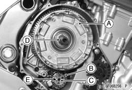
Clutch Housing [A] with Chain [B] and Sprocket [C] Sleeve [D] • Align [E] the hole on the oil pump sprocket with the oil pump shaft.
○Insert the sleeve into the clutch housing, noting its di- rection as shown. Sleeve [A] Oil Holes [B] Long Distance [C] Short Distance [D] Clutch Housing [E]
Clutch Hub [B] Washer [C] Nut [D]
○Replace the clutch hub nut with a new one. ○Holding the clutch hub, tighten the clutch hub nut.
|
|||||||||
|
|
Последнее изменение этой страницы: 2016-08-10; просмотров: 529; Нарушение авторского права страницы; Мы поможем в написании вашей работы! infopedia.su Все материалы представленные на сайте исключительно с целью ознакомления читателями и не преследуют коммерческих целей или нарушение авторских прав. Обратная связь - 3.144.252.140 (0.018 с.) |
 Clutch Cable Removal
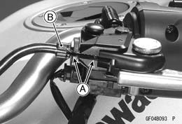 • Screw in the adjuster.
 • Disconnect the clutch cable clamp [A] on the cylinder head cover.
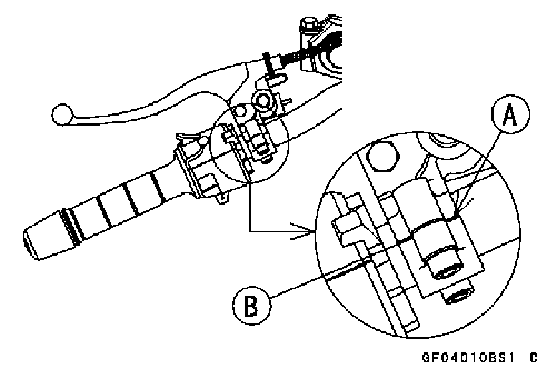 • Install the clutch lever so that the mating surface [B] of the clutch lever clamp is aligned with the punch mark [A].
 Clutch Lever Adjustment
 • Remove:
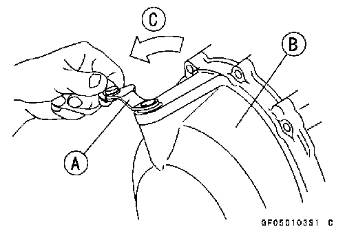 • Turn the release lever [A] toward the rear as shown, and remove the clutch cover [B].
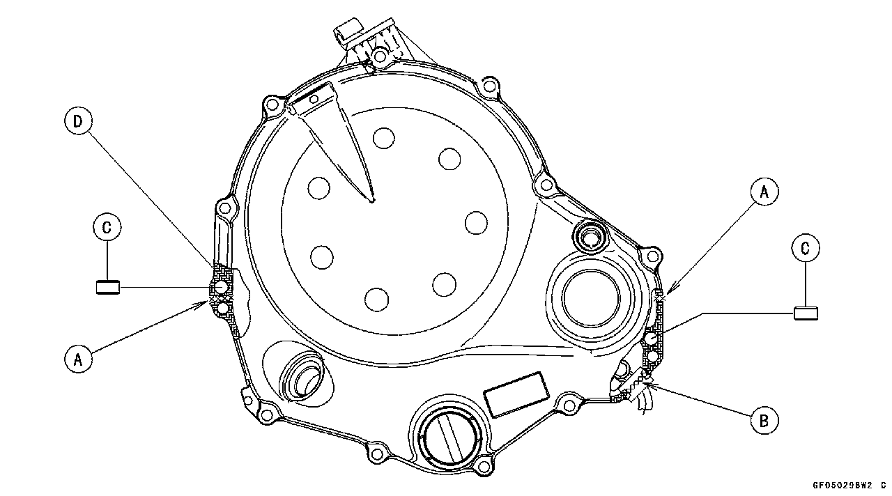
 Release Shaft Installation
 Clutch Cover [C]
 Clutch Cover Disassembly
 • Remove the oil level gauge [A].
 Clutch Cover Assembly
 • Apply water to the rubber of the oil gauge [A] and press [B] it so that the ring [C] face outside.
 • Remove:
 • Remove:
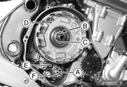 • Remove the oil pump sprocket bolt [A].
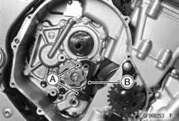 • Unscrew the bolts [A] and remove the oil pump chain guide [B].
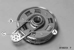 Clutch Installation
 • Insert the following on the drive shaft.
 NOTE
NOTE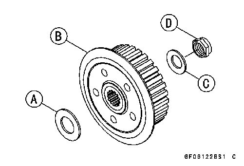 • Install the following parts on the drive shaft. Spacer [A]
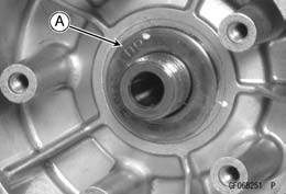 ○Install the washer so that the OUTSIDE mark [A] faces outward.