Заглавная страница Избранные статьи Случайная статья Познавательные статьи Новые добавления Обратная связь КАТЕГОРИИ: ТОП 10 на сайте Приготовление дезинфицирующих растворов различной концентрацииТехника нижней прямой подачи мяча. Франко-прусская война (причины и последствия) Организация работы процедурного кабинета Смысловое и механическое запоминание, их место и роль в усвоении знаний Коммуникативные барьеры и пути их преодоления Обработка изделий медицинского назначения многократного применения Образцы текста публицистического стиля Четыре типа изменения баланса Задачи с ответами для Всероссийской олимпиады по праву 
Мы поможем в написании ваших работ! ЗНАЕТЕ ЛИ ВЫ?
Влияние общества на человека
Приготовление дезинфицирующих растворов различной концентрации Практические работы по географии для 6 класса Организация работы процедурного кабинета Изменения в неживой природе осенью Уборка процедурного кабинета Сольфеджио. Все правила по сольфеджио Балочные системы. Определение реакций опор и моментов защемления |
Service Limit: 83.10 mm (3.2716 in.)
• Measure the outside diameter [A] of each piston 18 mm (0.7087 in.) [B] up from the bottom of the piston at a right angle to the direction of the piston pin.
Piston Diameter Standard: 82.969 ~ 82.984 mm (3.2665 ~ 3.2671 in.) Service Limit: 82.82 mm (3.2606 in.)
• Check for uneven groove wear by inspecting the ring seat- ing.
• With the piston rings in their grooves, make several mea- surements with a thickness gauge [A] to determine piston ring/groove clearance. Piston Ring/Groove Clearance Top Standard: 0.03 ~ 0.07 mm (0.0012 ~ 0.0028 in.) Service Limit: 0.17 mm (0.0067 in.) Second Standard: 0.02 ~ 0.06 mm (0.0008 ~ 0.0024 in.) Service Limit: 0.16 mm (0.0063 in.)
• Measure the piston ring groove width. ○Use a vernier caliper at several points around the piston. Piston Ring Groove Width Top [A] Standard: 0.92 ~ 0.94 mm (0.0362 ~ 0.0370 in.) Service Limit: 1.02 mm (0.040 in.) Second [B] Standard: 1.01 ~ 1.03 mm (0.0398 ~ 0.0406 in.) Service Limit: 1.11 mm (0.044 in.)
• Measure the piston ring thickness. ○Use the micrometer to measure at several points around the ring. Piston Ring Thickness Top [A] Standard: 0.87 ~ 0.89 mm (0.0342 ~ 0.0350 in.) Service Limit: 0.80 mm (0.031 in.) Second [B] Standard: 0.97 ~ 0.99 mm (0.0382 ~ 0.0390 in.) Service Limit: 0.90 mm (0.035 in.)
NOTE ○When using new rings in a used piston, check for un- even groove wear. The rings should fit perfectly parallel to the groove sides. If not, replace the piston.
• Place the piston ring [A] inside the cylinder, using the pis- ton to locate the ring squarely in place. Set it close to the bottom of the cylinder, where cylinder wear is low. • Measure the gap [B] between the ends of the ring with a thickness gauge. Piston Ring End Gap Top Standard: 0.25 ~ 0.40 mm (0.0098 ~ 0.0157 in.) Service Limit: 0.7 mm (0.028 in.) Second Standard: 0.40 ~ 0.55 mm (0.0157 ~ 0.0217 in.) Service Limit: 0.8 mm (0.031 in.)
Throttle Body Holder Installation
• Install the clamps [B] as shown and so that their projec- tions fit [C] on the holes of the holders. ○Be sure that the clamp bolt heads [D] face outwards. • Tighten: Torque - Throttle Body Holder Bolts [E]: 12 N·m (1.2 kgf·m, 106 in·lb)
Muffler Body Removal
• Remove: Right Frame Cover (see Frame Cover Removal in the Frame chapter) • Remove the bolts and lift up the right footpeg stay [A].
• Remove: Lower Fairings (see Lower Fairing Removal in the Frame chapter) Center Fairings (see Center Fairing Removal in the Frame chapter) Muffler Body Clamp Bolt [A] Exhaust Pipe Manifold Holder Nuts [B] Exhaust Pipe [C] Gaskets
Muffler Body and Exhaust Pipe Installation • Replace the exhaust pipe gaskets [A] and muffler body connection gasket [B] with new ones and install them.
○Install the muffler body connection gasket until it is bot- tomed so that the chamfer side [C] feces muffler body [D]. • Install: Muffler Body Exhaust Pipe [E] • Tighten: Torque - Exhaust Pipe Manifold Holder Nut [F]: 17 N·m (1.7 kgf·m, 12 ft·lb) Muffler Body Mounting Bolts (Front and Rear) [G]: 20 N·m (2.0 kgf·m, 15 ft·lb) • Tighten the muffler body clamp bolt [H]. ○Install the muffler body clamp bolt as shown.
• Thoroughly warm up the engine, wait until the engine cools down, and retighten all the bolts and nuts.
Clutch Table of Contents Exploded View........................................................................................................................ 6-2 Specifications......................................................................................................................... 6-4 Special Tool and Sealant........................................................................................................ 6-5 Clutch Lever and Cable.......................................................................................................... 6-6 Clutch Lever Free Play Inspection.................................................................................... 6-6 Clutch Lever Free Play Adjustment.................................................................................. 6-6 Clutch Cable Removal...................................................................................................... 6-6 Clutch Cable Installation................................................................................................... 6-6 Clutch Cable Lubrication................................................................................................... 6-6 Clutch Lever Installation.................................................................................................... 6-7 Clutch Lever Adjustment................................................................................................... 6-7 6 Clutch Cover........................................................................................................................... 6-8 Clutch Cover Removal...................................................................................................... 6-8 Clutch Cover Installation................................................................................................... 6-8 Release Shaft Removal.................................................................................................... 6-9 Release Shaft Installation................................................................................................. 6-9 Clutch Cover Disassembly................................................................................................ 6-9 Clutch Cover Assembly..................................................................................................... 6-10 Clutch..................................................................................................................................... 6-11 Clutch Removal................................................................................................................. 6-11 Clutch Installation.............................................................................................................. 6-11 Clutch Plate, Wear, Damage Inspection........................................................................... 6-13 Clutch Plate Warp Inspection............................................................................................ 6-14 Clutch Spring Free Length Measurement......................................................................... 6-14
Clutch Housing Finger Inspection..................................................................................... 6-14 Clutch Housing Spline Inspection..................................................................................... 6-14
CL: Apply cable lubricant. EO: Apply engine oil. G: Apply grease. HG: Apply high-temperature grease. L: Apply a non-permanent locking agent. Lh: Left-hand threads M: Apply molybdenum disulfide grease. R: Replacement Parts S: Follow the specified tightening sequence. W: Apply water.
|
||||||||||||||||||||||||||||||||||||||||||||||||||||||||||||||||||||||||||||||||||||||||||||||||||||||
|
|
Последнее изменение этой страницы: 2016-08-10; просмотров: 389; Нарушение авторского права страницы; Мы поможем в написании вашей работы! infopedia.su Все материалы представленные на сайте исключительно с целью ознакомления читателями и не преследуют коммерческих целей или нарушение авторских прав. Обратная связь - 3.144.12.14 (0.014 с.) |
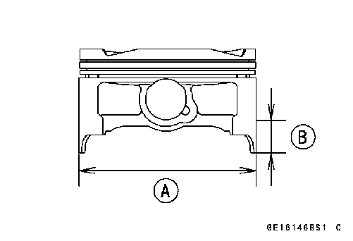 Piston Wear
 If the measurement is under service limit, replace the pis- ton.
 Piston Ring, Piston Ring Groove Wear
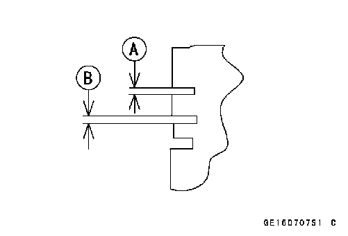 Piston Ring Groove Width
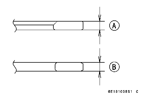 Piston Ring Thickness
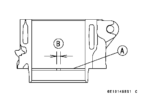 Piston Ring End Gap
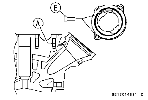 • Be sure to install the O-rings [A].
 Muffler
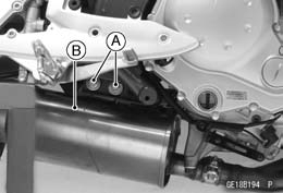 • Remove the muffler body mounting bolts [A] and nut, and pull the muffler body [B] backward.
 Exhaust Pipe Removal
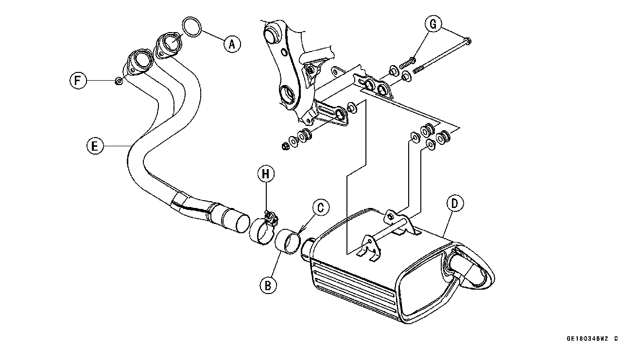

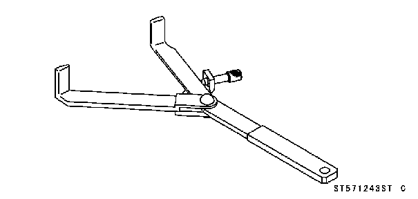
 Clutch Holder: 57001-1243