Заглавная страница Избранные статьи Случайная статья Познавательные статьи Новые добавления Обратная связь КАТЕГОРИИ: ТОП 10 на сайте Приготовление дезинфицирующих растворов различной концентрацииТехника нижней прямой подачи мяча. Франко-прусская война (причины и последствия) Организация работы процедурного кабинета Смысловое и механическое запоминание, их место и роль в усвоении знаний Коммуникативные барьеры и пути их преодоления Обработка изделий медицинского назначения многократного применения Образцы текста публицистического стиля Четыре типа изменения баланса Задачи с ответами для Всероссийской олимпиады по праву 
Мы поможем в написании ваших работ! ЗНАЕТЕ ЛИ ВЫ?
Влияние общества на человека
Приготовление дезинфицирующих растворов различной концентрации Практические работы по географии для 6 класса Организация работы процедурного кабинета Изменения в неживой природе осенью Уборка процедурного кабинета Сольфеджио. Все правила по сольфеджио Балочные системы. Определение реакций опор и моментов защемления |
Finding the Best CombinationСтр 1 из 10Следующая ⇒
Finding the Best Combination Large quantities of raw material are produced in various types of surface operations. Where the product is rock, the operations are known as quarries. Where metallic ore or non-metallic minerals are involved, they are called open pit mines. There are many common parameters in design and choice of equipment, and in the process of finding the best combination of drilling and blasting methods. Atlas Copco has the advantage of long experience in all types of surface drilling operations, with a product range to match. With its history of innovative engineering, the company tends to think forward, and is able to advise the user on improving design elements of the operation that will result in overall cost savings. Quarries A quarry is a factory that converts solid bedrock into crushed stone. The excavated rock is crushed, screened, washed and separated into different sizes, for subsequent sale and use. The amount of fines should be kept to a minimum. The final products are used as raw material for chemical plants, such as limestone for cement manufacturing, paper and steel industries, and clay shales for building materials, or as raw material for concrete aggregates, highway construction, or other civil engineering projects. Not all types of rock are suitable as raw material for crushed stone. The material must have certain strength and hardness, and the pieces acquire a defined shape with a rough surface. Consequently, soft sedimentary rock, and material which breaks into flat, flaky pieces, are unacceptable. Igneous rock such as granite and basalt, as well as old Precambrian highly metamorphic rock such as gneiss, are well suited. Quarries are normally run by operators who sell their products to nearby contractors and road administrators. This means that in areas where construction activities are high, several competing quarries may be established. Apart from environmental aspects, such operations can disturb the neigh bouring area in the form of noise from drilling, vibrations from blasting, and dust from crushing and screening. Quarries, wherever possible, are therefore discreetly located, as close as feasible to the construction area, because the products are transport cost sensitive. Quarries can be either of the common pit type or, in mountainous terrain, the hillside type. Pit type quarries are opened up below the level of surrounding terrain, and accessed by means of ramps (Figure 1). The excavation is often split into several benches, depending on the depth of the operations. In its first stage, when the terrain is rough and bulldozers cannot provide a flat floor, a top-
hammer construction type drillrig can be used to establish the first bench. Once the first bench is prepared, production drilling is preferably carried out using DTH- or COPROD techniques. Shallower Benches Whereas high benches, above 30 m, were previously quite common, nowadays they are shallower, for improved safety and economy. The width of the bench should be sufficient both to accommodate the spread of rock blast, and to provide space for the equipment. The height of the working face in hill-type quarries is determined mainly by the topography. A typical work cycle in a quarry consists of a number of work elements. Drilling of blastholes is undertaken in a predetermined pattern, followed by plugging the drill holes with wooden or plastic plugs to prevent debris from falling down into the holes. When an adequate number of holes have been drilled, preparations for blasting will start. The holes are blown clean with compressed air to remove water and rock fragments, and are then charged with a booster bottom charge, detonators and explosives. Stemming is inserted into the top of each hole, and the detonator leads are connected. Where electric detonators are used, thе circuit resistance is checked with an ohmmeter. The area is evacuated, equipment is moved away, and the round is fired.
The different products, comprising rock fragments of certain size ranges, are recovered from the process by vibrating screens, and transported to storage silos or bunker piles on the ground. Optimum Efficiency There are various factors to be considered when trying to achieve optimum efficiency and overall economy from quarrying operations, the most important of which is cost reduction. Figure 2 illustrates a typical cost distribution between drilling and blasting, loading and transport, and crushing, screening and storage. It should be noted that crushing, screening and storage represent about half of the costs, whereas drilling represents less than 10%. More often than not, the crushing operation is the bottleneck in the total workcycle. *It is sometimes the case that extra expenditure in drilling and blasting might be the only way to assure free flow through the crusher, in order to utilize full capacity in the plant, and improve overall economy. From an economics viewpoint, however, it is obvious that large-size crushers are primarily designed to handle large amounts of rock material, rather than large-size material. Therefore, it is worth assessing the rock fragmentation derived from the drilling and blasting cycle, in case some additional investment in drilling is the answer (Figure 3). The whole chain of activities lead-ing to the final product of crushed material must be considered when optimizing total costs. Drilling costs depend on the hole size and drilling density, in which accuracy of drilling is a factor; blasting costs depend on the amount and type of explosives, and number of detonators; and loading, transport and crushing costs depend on quarry floor roughness, and fragmentation.
For most drilling applications, the optimum ratio between bench height and burden seems to be in the range of 3 to 4, indicating that hole diameters of 125-165 mm (5-6 in) are best for a bench height in the order of 18 m. Figure 4 shows the trends in choice of drilling method. There is a clear movement towards more hydraulic tophammer, COPROD-drilling and DTH, and away from pneumatic and rotary drilling. Open Pit Mining A major difference between open pit mining and quarries is the geological conditions and the demand characteristics on the blasted material. Whereas quarries deliver the majority of rock via the crushing and screening plant in various size fractions, the open pit mine attempts to deliver the ore as pure as possible via crushers to the dressing plant, consisting of mills, separators, and/or flotation, and/or biochemical systems, and finally to smelters, in order to convert minerals to metals. As no orebodies have the perfect conical shape which is tailor-made for the geometry of a pit, vast quantities of waste usually have to be removed from both the hangingwall and the footwall in order to mine the ore. Figure 5 shows a sectional layout of a typical pit. The waste-to-ore ratio increases as the pit gets deeper. Eventually, for economic reasons, the open pit will be abandoned, or underground mining will take over. Without jeopardizing slope stability, it is of prime importance to keep the pit slope angle as steep as possible, maintaining excavated waste at a minimum. The demands on fragmentation of the waste, as it will not pass through the crushing/dressing system, are simple. It should merely suit the loading and trucking equipment used forsubsequent removal to the waste dump. On the other hand, good fragmentation of the blasted ore will make great savings in the total costs of the mineral dressing process.
Steep and Stable Slopes Blasting will not only break the rock that is planned to be excavated, but will also cause damage to the slopes that form the boundaries of the pit. The extent of this overbreak is mainly dependent on the size of the individual charge and its proximity. A common means of minimizing overbreak is to use smaller diameter holes, making pro-vision for restricted blasting in the zone next to the planned bench slope. Figure 6 shows two different blast designs. Figure 7 shows a typical drilling pat-tern to be applied in connection with pre-split blasting, to achieve increased slope stability with reduced back break.
Drilling Patterns Traditionally, focusing on the drilling cost parameter, the predominant method in open pit mining has been large hole rotary drilling using hole sizes in the 250 to 400 mm (10-15.75 in) range. No doubt this implies lower cost for drilling, ignoring the expense of excess waste and less favourable fragmentation. A recent survey of 36 open pit operations in Chile using hole sizes between 75 and 345 mm (3.0-13.75 in) reveals that hole sizes above 200 mm (8 in) do not generate any substantial savings in total drilled metres per tonne. This indicates that burden and spacing cannot be increased indefinitely. One important reason for replacing rotary with other methods is the inflexibility of the heavy rotary rigs, which are restricted to vertical benches and single pass drilling only. A possible, but not advisable, step in obtaining smaller holes, is to adapt rotary rigs to DTH drilling, by adding a high-pressure compressor to the rig. As the need for wide benches to cope with the inflexibility of the rotary rig still remains, this measure will not derive the full potential benefits of the DTH drilling method. Figure 8 shows the advantages related to using an Atlas Copco ROC L8 rig, having the ability to drill inclined holes close to the bench wall, compared to a traditional rotary rig. Souffle Blasting Mining of rich, narrow and irregularly stratified ore zones, such as gold mineralizations, requires extra attention, in order not to introduce unnecessary quantities of waste into the ore stream. Consequently, this type of mining has to be progressed on a selective basis, in close liaison with surveyors and geologists, and taking frequent samples before and after each individual blast. Short benches and small holes are used to cope with ore zone irregularities. A recently-developed method to ensure maximum recovery from each blast is called souffle blasting. Figures 9 illustrate this principle of cautious blasting with a minimum of dilution as practised at the Bjorkdal gold mine in Sweden. To a depth of merely 5 m, 100 vertical holes are blasted in one round, without free surface for expansion. The firing sequence starts in the centre and, thanks to 2.5 m of stemming, the blasted ore material just swells on site like baking a souffle. Selective extraction by backhoe loaders facilitates maximum recovery of the rich, narrow gold-bearing zones. Lists of words
1. quantity –маса 2. quarry – кар’єр 3. working face – очисний вибій 4. crushing – дроблення 5. dilution - розубоження 6. bench -уступ 7. spread – простір, простягання 8. stemming – набивання шпура 9. charge -заряд 10. hanging wall – висячий бік
11. footwall – лежачий бік 12. stability – стійкість 13. waste to ore ratio – коефіцієнт розкриву 14. cautious - обережний 15. waste – пуста порода 16. burden – лінія найменшого опору 17. fragmentation - фрагментація 18. overburden – розкрив 19. slope - похил 20. resistance – опір Exercises: 1) Give the definitions of the following terms: Quarry; open pit; surface operations; cost savings. 2) Read and give Ukrainian equivalents of the following international words: Parameters, design, process, combination, method, operations, location, material, critical. 3) Match a word in column A with a definition in column В: 1. a quarry 1. грохотіння 2. crushing 2. кам'яний кар'єр 3. screening З. подрібнення 4. separation 4. сепарація 5. raw material 5. осадочна порода 6. types of rock 6. метаморфічна порода 7. metamorphic rock 7. сировина
8. sedimentary rock 8. прилягаюча площа 9. neighbouring area 9. типи порід 10. feasible 10. економічно вигідний 4) Complete the following sentences: 1) A quarry is a factory that converts..... 2) The final products are used....... 3) Quarries are normally run by......... 4) The excavation is often split into several benches...... 5) A typical work cycle in a quarry.......... 5) Tell what you know about: 1) Quarries 2) Shallow Benches 3) Optimum Efficiency 4) Open Pit Mining 5) Steep a Stable Hopes Principles of Rock Drilling This reference edition deals with surface rock drilling used for the purpose of excavating rock by means of blasting. Other types of drilling, such as drilling for oil and water, mineral exploration, and grouting are excluded. The reader is given a brief explanation of the various prevailing drilling methods, as well as an introduction to blasting technique, and the interrelation of drilling and blasting. Also discussed are the main parameters involved when planning and executing blasthole drilling at quarries, open pit mines and various types of civil engineering projects.
The range of Atlas Copco products, with references to the Atlas Copco internet home pages, are presented and discussed by comparing their suitability and expected productivity related to various applications. Updated case stories from different worksites in the world should prove interesting and beneficial, when planning and selecting methods and equipment for blasthole drilling applications.
Blastholes have certain unique and important characteristics. These are: hole diameter, hole depth, direction and straightness. Drilling produces a circular hole n the rock, whose strength must be overcome by the drilling tool. Depending on rock properties, there are several ways to accomplish this, as shown in the following article.
Rotary Drilling Rotary drilling can be subdivided into rotary cutting and rotary crushing. Rotary cutting creates the hole by shear forces, breaking the rock's ten sile strength. The drillbit isfurnished with cutter inserts of hard metal alloys and the energy for reaking rock is provided by rotation torque in the drillrod. This technique is limited to rock with low tensile strength, such as salt, silt, and soft limestone not containing abrasive quartz minerals. Rotary crushing breaks the rock by high point load, accomplished by a toothed drillbit, which is pushed downwards with high force. The bit, being of tricone roller type fitted with tungsten carbide buttons, is simultaneously rotated, and drill cuttings are removed from the hole bottom by blowing compressed air through the bit. Drillrigs used for rotary drilling are large and heavy. The downwards thrust is achieved by utilizing the weight of the drillrig itself, and the rotation, via a hydraulic or electric motor, applied at the end of the drill pipe. Common hole diameters range from 8 to 17.5 in (200-440 mm) and, because adding the heavy drill pipes is cumbersome, most blasthole drillrigs use long masts and pipes to accommodate single-pass drilling of maximum 20 m (65 ft). Electric power is usually chosen for the large rigs, whereas smaller rigs are often powered by diesel engines. Rotation rates vary from 50 to 120 rev/min, and the weight applied to the bit varies from 0.5 t/in of bit diameter in soft rock, to as much as 4 t/in of bit diameter in hard rock. Recent technical advances include: improved operator cab comfort; automatic control and adjustment of optimum feed force and rotation speed to prevailing geology and bit type and diameter; and incorporation of the latest technology in electric and hydraulic drive systems. Rotary drilling, which is still the dominant method in large open pits, has limitations in that the rigs are not suited to drilling holes off the vertical line. As blasting theories and practice have proved, it is generally beneficial to design, drill and blast the bench slopes at an angle of approximately 18 degrees off vertical. Many rotary rig masts have pinning capabilities permitting drilling at angles as much as 30 degrees out of the vertical. However, the inclined hole drilling capabilities in rotary drilling are limited by the heavy feed force required, since part of this force is directed backwards. This causes rig stability problems, reduced penetration, and shorter life of drilling consumables. Consequently, most blast hole drilling using rotary drillrigs is for vertical holes. Percussive Drilling Percussive drilling breaks the rock by hammering impacts transferred from the rock drill to the drillbit at the hole bottom. The energy required to break the rock is generated by a pneumatic or hydraulic rock drill. A pressure is built up, which, when released, drives the piston forwards. Figure 1 illustrates the principle of top hammer percussive drilling. The piston strikes on the shank adapter, and the kinetic energy of the piston is converted into a stress wave travelling through the drill string to the hole bottom. In order to obtain the best drilling economy, the entire system, rock drill to drillsteel to rock, must harmonize.
Stress Wave Theoretically, the stress wave has a rectangular shape, the length of which is twice that of the piston, while the height depends on the speed of the piston at the moment of impact, and on the relationship between the cross-sectional area of the piston and that of the drillsteel. The total energy that the wave contains is indicated diagramatically in Figure 2. To calculate the output power obtained from a rock drill, the wave energy is multiplied by the impact frequency of the piston, and is usually stated in kW. Rock drill designers seek to find the best combinations of various parameters, such as the piston geometry, the impact rate and the frequency. Two rock drills having the same nominal power rating might therefore have quite different properties.
The shock waves that are generated by hydraulic (Figure 3) and pneumatic (Figure 4) rock drills are significantly different in shape. Drillrods used with hydraulic rock drills will normally show substantially longer service life, compared with pneumatic rock drills, because of the higher stress level obtained with the pneumatic driven piston. The reason is the larger cross-section needed when operating at substantially lower pressure, which is 6-8 bars, compared to the 150-250 bars used with hydraulic systems. The slimmer the piston shape, the lower the stress level. Figure 5 compares the stress level generated by three different pistons having the same weight, but with different shapes and working at different pressures. The lowest stress, or shock wave amplitude, is obtained with the long slender piston working at high pressure.
Efficiency and Losses The wave loses some6-10% of its energy for even, additional coupling, as it travels along the drillstring. This loss is partly due to the difference in cross-sectional area between the rod and the sleeve, and partly due to imperfect contact between the rod faces. The poorer the contact, the greater the energy loss. When the shock wave reaches the bit, it is forced against the rock, thereby crushing it. The efficiency at the bit never reaches 100%, because some of the energy is reflected as a tensile pulse. The poorer the contact between the bit and the rock, the poorer the efficiency (Figure 6).
To optimize drilling economy, the drilling parameters for percussion pressure, feed force, and rotation must harmonize. Percussion Pressure The higher the pressure, the higher will be the speed of the piston, and consequently, the energy. Where the bit is in good contact with hard and competent rock, the shock wave energy can be utilized to its maximum. Conversely, when the bit has poor contact, the energy cannot leave the drillstring, and reverses up the drill-string as a tensile wave. It is only when drilling in sufficiently hard rock that the maximum energy per blow can be utilized. In soft rock, to reduce the reflected energy, the percussion pressure, and thus the energy, will have to be lowered (Figure 7). For any given percussion pressure, the amplitude, and hence the stress in the drillsteel, will be higher with reduced cross-section of the drillrods.
To get the longest possible service life from shank adapters and rods, it is important to ensure that the working pressure is matched to the drillstring at all times. Feed Force The purpose of the feed is to maintain the drillbit in close contact against the rock. However, the bit must still be able to rotate. The feed force must always be matched to the percussion pressure. Figure 8 illustrates this relationship. Rotation The purpose of rotation is to turn the drillbit to a suitable new position for the next blow. Using button bits, the periphery is turned about 10 mm between blows. Consequently, the rotation rate is increased using higher impact frequency and reduced bit diameter. Using insert bits, the recommended rotation rate is 25% higher. Setting Parameters In practice, the driller sets the percussion pressure that the rock can cope with, and then sets the rev/min with regard to the percussive frequency and the bit diameter.
When drilling starts, the feed is adjusted to get even and smooth rotation. In case this is not achieved, which will show up in low shank adapter life, the percussion pressure can be progressively reduced, until even and smooth rotation is reached. The temperature of the adapter sleeve can be checked to ensure that the drilling parameters are correctly set. Immediately after drilling, the temperature should be 60-70 degrees for dry drilling, and approximately 40 degrees for wet drilling. Drilling problems, mainly related to loose couplings, may arise whatever parameters are used. In order to tighten the couplings during drilling, the friction of the bit against the hole bottom has to be increased. This can be done by increasing the feed, increasing the rotation rate, or changing the bit. Flushing Drill cuttings are removed from the hole bottom to the surface by air blowing or water flushing. As the power output from rock drills increases, accompanied by increased penetration rate, efficient flushing becomes gradually more important. The flushing medium is normally air for surface drilling, and water for underground drilling.
The required flushing speed will depend on: specific gravity - material having a density of 2 t/cu m requires at least 10 m/sec, whereas iron ore, for example, having a density of 4 t/cu m, requires an air speed of 25-30 m/sec; particle size - the larger the particles, the higher flushing speed required; particle shape -- spherical particles require more speed than flaky, leaf shaped particles. Productivity and Methods During the past century there has been a rapid and impressive increase in efficiency and productivity related to top hammer drilling. Starting from hitting a steel manually by a sledge hammer 100 years ago, today's hydraulically powered rock drills utilize the latest state-of-the-art technology. Every drilling method has its pros and cons, making an objective comparison quite cumbersome. In view of this, the table in Figure 9 can serve as a guideline when comparing the various percussion drilling alternatives which Atlas Copco can offer. The choice of best drilling method to apply depends on hole size and type of application.
Lists of words
1. drilling – свердлування, буріння 2. rotary – ротаційний 3. rock – скеля, гірська порода 4. percussive –ударний 5. stress – тиск, напруження 6. rod – штанга 7. rotation –обертання 8. flushing - змивання 9. specifiс gravity – питома вага 10. pressure – тиск 11. drillstring – буровий снаряд 12. approximately - приблизно 13. drill cuttings – буровий дрібняк 14. hydraulically - гідравлічно 15. density – щільність, густина 16. penetration - проникнення 17. frequency - частота 18. relationship - взаємовідношення 19. accomplish – здійснювати Exercises: 1) Give the definitions of the following terms: Drilling, excavation, blast hole characteristics. 2) Read and give Ukrainian equivalents of the following international words: Reference, excavating, method, interrelation, technique, planning, engineering, present, productivity, rotary, diameter, pneumatic, hydraulic. 3) Match a word in column А with a definition in column В: 1. drillrigs 1. буровибухова свердловина 2.blasting technique 2. діаметр свердловини 3. blasthole 3. 6ypoвий станок 4. hole diameter 4. бурова коронка 5. rotary drilling 5. методи буро-вибухових робіт 6. bit 6. похиле буріння 7. technical advances 7. роторне буріння 8. inclined hole drilling 8. nepepiз 9. crosscection 9. новi технічні рішення 10. drilling parameters 10. параметри буріння 4) Complete the following sentences: 1) Rotary drilling can be subdivided into....... 2) Drillrigs used for rotary drilling are........ 3) Rotation rates vary from......... 4) Percussive drilling breaks the rock......... 5) The higher the pressure, the higher.......... 5) Tell what you know about: 1) Rotary Drilling 2) Percussive Drilling 3) Efficiency and Losses 4) Rotation 5) Productivity and Methods Ergonomics and Safety
Drilling Efficiency Efficient drilling is a function of many individual aspects, both mechanical and human. While it is necessary to have a powerful and easily-maneuverable drillrig, it is also important to take good cary of the operator's needs, and those of the external environment. What value is a machine that is too noisy, or cannot be operated in harsh weather? Operator comfort and safety has to be planned into the modern drilling at the drawing board stage of design. To get maximum return on investment, the owner needs to be sure that the drillrig is designed to work in all conditions, without the operator getting unduly tired, and with minimum disturbance of the environment in the neigh bourhood of the site. All Atlas Copco drill-rigs are designed with these parameters in mind. In addition, a whole array of options is available to control the inclination, alignment and depth of drillholes, in order to get the maximum rock breaking effect from the minimum drilling effort, reducing noise and dust, and saving time, money, and materials. Operator's Cabin The interplay between man and machine starts in the operator's cab, and Atlas Copco has expended great effort in the development of a well conceived, purpose-built cab. Even the smallest details have been considered to produce a modern workstation, not only' in terms of mechanical function, but also paying attention to the requirements of ergonomics, safety and the environment. The cabin offers a superb view of the drillhole from the operator's seat, facilitating accurate collaring and control of the drilling operation. The angled, laminated glass windscreen is equipped with a large wiper, as are the right hand side and roof windows, and improved air ventilation effectively clears condensation mist from all of these windows. A jumbo-sized rear-view mirror gives good visibility and safer rig moving. In addition, the spacious cab gives good moveability and comfort for the operator, with easy-to-read instrumentation that is simple to learn and to use. A mechanized tube-permutation system enables any damaged drill rods to be identified from the operator's cab. The service hatches are easily accessed, but are also lockable, as a good security precaution at isolated worksites. The cabins are even equipped with a 12-volt outlet for mobile telephone. Ergonomics and Environment The cabin is laid out so that the operator can monitor and control the entire drilling process without changing body position. This relieves neck, shoulders and back from strain. The ergonomically-designed seat is vertically and laterally adjustable, with control levers and control panel located in, or in close proximity to, the collapsible arm rests. The seat is slewable for easy entry into the cab, and the door is fitted with a safety stop that prevents crushed fingers. Good insulation affords a noise level below 80 dB, and rubber-damping of the cab mounting reduces vibration and gives greater comfort during tramming. The cabin has an efficient CFC-free air conditioning system for both cooling and heating, and many surfaces are textile covered for greater comfort.
(ROPS) and Falling Object Protective Structure (FOPS). With regards to the environment, exhaust emission values of all new Atlas Copco drillrigs are lower by a good margin than those stipulated in international standards, as are the noise values. There is efficient dust collection and coarse separation, the feeds are fitted with collectors for lubricating oil, and biologically degradable hydraulic oils are available as options. Hole Alignment Regulations governing rock blasting in open-air excavations are found in countries all over the world. Rock excavation by drilling and blasting is a particular menace in quiet, urban areas, and it is strictly governed with respect to allowable levels of pressure shocks and ground vibrations. Productivity, and the need to control ground vibrations, means that capable and precise instruments are required to guide the driller. Faults in blasthole direction, hole deviations, and variations in hole depths must be minimized, if efficient production is to be obtained. Instruments for angle set-ting and hole depth control increase drilling accuracy and reduce human error. There are various ways for a con-tractor to comply with the blasting rules, without increasing costs for rock excavation. Several benefits can be obtained from improved blasthole alignment and drill depth control. Improved accuracy in the application of the drilling pattern saves time, drill-metres, and explosives. At the same time, less boulders need to be broken, and less crushing of oversize is required. All this means reduced operating cost, and money saved. A modern hole alignment instrument offers: more precise drilling with a reduction in cost/hole; automatic depth control; better fragmentation; automatic drill feed stop; flat benches after blasting; and less overdrilling. By guaranteeing a perfect blast result, there is no need for the contractor to return and clean up rough surfaces, or condition overbreak. Much blasting inconvenience can be reduced by special drilling patterns, which distribute the explosive charges evenly, and limit the level of ground vibrations, so as not to harm property in the vicinity. To achieve this, it is crucial to collar the hole on the right spot, maintain the correct alignment, and drill to a predetermined level. Depth Control The alignment instrument confirms the hole angle, while a laser sensor monitors drilling to the proper depth, regardless of the surface conditions. All this comes together for a successful blast, breaking rock to a level floor, with minimum ground vibration, and even fragmentation. The HQS and the HEC3 angle set-ting instruments, used with the aiming device, helps set the correct angle of inclined holes. The angle and hole depth reader function controls the length of a blast hole, from the start of the hole on surface, to the preset bottom elevation. The instrument does not require any assistance from the operator, and comes with an automatic drill feed stop function for optimum drilling accuracy. The instruments feature automatic compensation, regardless of the drilling surface ground conditions. A beacon, mounted on a tripod, generates a horizontal reference plane on a 350 m radius across the worksite by a rotating laser beam. A sensor, fitted to the rock drill cradle, reacts to the signal generated by the rotating laser beam. The HQS 12 instrument pro-vides a reference plane for all holes, automatically adjusting hole depth to match the plan, with an accuracy within 5 cm.
Lists of words
1. efficiency –продуктивність 2. operator - машиніст 3. environment – навколишнє середовище 4. alignment – вирівнювання, вивіряння 5. cradle - рама 6. vibration - вібрація 7. margin –край 8. degrade - руйнувати 9. blast – вибух 10. adjusting – пристрій
11.collaring - забурювання 12. boulder - негабарит 13. condition - умова 14. pattern - контур 15. hole deviation – відхилення свердловини 16. worksite - робоче місце 17. insulation - ізоляція 18. fragmentation - фрагментація 19. dust collection - пиловловлювання 20. drill feed – подача бура Exercises: 1) Give the definitions of the following terms: Ergonomics, drilling efficiency, operator comfort 2) Read and give Ukrainian equivalents of the following international words: Ergonomics, efficiency, function, individual aspect, mechanical, human, comfort, modern, maximum, conditions. Match a word in column A with a definition in column В: 1. both mechanical and human aspect 1. зменшення шуму та пилу 2. to get maximum return 2. увесь процес буріння 3. reducing noise and dust 3. i механічний i людський аспект 4. entire drilling process 4. вщповщати:шжнародним вимогам з охорони праці 5. air conditioning system 5. точні інструменти 6. compile with international 6. напрям бурової свердловини 7. precise instruments 7. лазерний сенсор 8. blasthole direction 8.витрати на видобуток руди 9. costs for ore excavation 9. система кондищювання повітря 10. laser sensor 10. отримати максимальну віддачу 4) Complete the following sentences: 1) Operator comfort and safety..... 2) To get maximum return on....... 3) The cabin offers.......................................................... 4) The cabin is laid out so that..... 5) Productivity, and the need to control..........
5) Tell what you know about: 1) Drilling efficiency 2) Operator's cabin 3) Ergonomics and Environment 4) Hole alignment 5) Depth control
Construction in Rock In civil engineering, as well as in the building industry, rock is removed to make place for new roads and railways, house foundations, ports and airports, trenches and pipelines, or to provide material for breakwaters and concrete aggregate. These types of construction projects differ from quarrying and open pit mining, in that bench heights vary continuously. Drilling is often performed from a rugged and steep rock surface, which means that the equipment used must have good terrain travelling characteristics. Also, as several holes are drilled from one rig setup, folding booms having good coverage in various directions and planes are the preferred equipment. Atlas Copco has a complete range of drillrigs for this type of work, from heavy crawler rigs to lightweights that can be craned into position, if necessary. The whole spectrum of drilling methods is also available, from pneumatic handheld to hydraulic tophammer, COPROD and DTH.
Before a new project is commenced, it is normal routine that a design and preinvestigation is conducted, coupled with allocation of financing. Most civil engineering projects are subject to a tendering procedure, where scope of work, bill of quantities, drawings, geological information and time schedule are disclosed, to give all interested parties standard information on which to base their bids. The con-tractor, or a consortium of contractors, makes its calculations based on evaluating equipment requirements, methods, availability of skilled labour, time schedule, local conditions and regulations, as well as cost estimates. Past experience derived from similar projects plays an important role in estimating future costs. A project involves a wide range of equipment, and clever selection is important to achieve overall optimum performance. For blasthole drilling, the variation and complexity of blasting parameters might require both heavy crawler drills and hand held rock drills. The equipment should, however, be selected to cover a wide range of applications, which will improve spare parts handling and maintenance procedure, and the prospects for usage in subsequent projects. Tophammer drilling rigs are normally the first choice, due to their flexibility, versatility and ability to drill holes of small diameter. Road Excavation
Figure 1 shows a typical drilling and blasting pattern for a road cut where special emphasis is placed on the final rock wall contour. Smooth blasting, or presplitting, are commonly used, and quite often specified in the tendering documents, to obtain smooth and stable side contours. Contour holes are normally not larger than 64 mm, with spacing of less than 1 m, and charging is carried out using special, light explosive to mini-mize the effect of shock waves. Initiation is frequently by detonating cord. Presplit holes are fired simultaneously ahead of the other holes, where-as smooth blasting uses the highest number of detonator delay. Presplitting creates an artificial plane along the limits of the excavation, against which the subsequent main blast may break, resulting in a smooth wall, with little or no over-break. Some of the shock waves from the subsequent main blast are reflected against the presplit plane, preventing them from being transmitted into the remaining rock. This also tends to reduce ground vibrations. Drilling with high precision is of utmost importance for the final result. Slope stabilization should normally be carried out as an integrated part of the excavation process. Horizontal drilling, anchoring, grouting, and meshing using elevated working platforms could cause excessive costs and delays, where they have to be conducted at a later stage (figure 2). Urban Blasting Several precautions have to be taken when excavating in built-up areas close to population, infrastructure, buildings and installations (figure 3). It is quite common that special blasting consultants are involved, to assist the contractor with vibration control and design of drill patterns, as well as a thorough survey of adjacent structures before the work can commence. To minimize ground vibrations, the drillholes are kept as small as possible, normally 30-50 mm diameter. To eliminate the risk of fly rock, the blasts are covered with heavy mats made of logs, rubber, or tyres, cut into sections and twined together with steel wires. These mats, of around 1 t weight, are energy absorbing. The gases produced by the blast ventilate through the mats without displacing them.
Trenching Trenches are excavated for installation of oil, water and sewage pipelines, as well as for cables. Blasting of trenches differs from common bench blasting, because the width of the round is considerably smaller than its length. Trench blasting is defined as rounds with a width of less than 4 m.A trench blast is more constricted than a normal open pit blast, which results in higher explosives consumption per cubic metre of blasted rock. The diameter of the blast holes is normally smaller, which provides better distribution of the explosive in the rock, and avoids excessive overbreak outside the theoretical contour. As a rule of thumb, the hole diameter should be one sixtieth of the width of the trench, so if the width is 2.0 m, the diameter of the hole should be 33 mm. Two methods are used for trench blasting: traditional and smooth wall. In traditional trench blasting, the middle hole/holes are placed in front of the lateral holes. All holes are charged with the same amount of explosives. In smooth wall trench blasting, all holes in each row are in line. The middle hole/holes are quite heavily charged, while the edge holes have light charges. Blasting of trenches in urban areas requires careful planning and precautions. A typical drilling pattern and blasting sequence is shown in figure 4 overleaf. Overall project costs and tight time schedule are of highest priority when conducting pipeline projects for oil and gas distribution in unpopulated areas, and larger blastholes are used, as shown in figure 5 overleaf.
Lists of words 1. bench hight – висота уступу 2. boom - стріла 3. complexity - складність 4. trenching – проходка траншей 5. tender – пропозиція 6. shock wave - ударна хвиля 7. initiation - ініціювання 8. subsequent - наступний 9. precision - точність 10. blasting – підривні роботи 11. eliminate - усувати 12. constrict - стягувати 13. sequence - послідовність 14. anchoring- закріплення 15. bid – заявка, пропонування 16. planning - планування 17. charge - заряджати Exercises 1) Give the definitions of the following terms: Civil engineering, drillrig, drilling method. 2) Read and give Ukrainian equivalents of the following international words: Engineering, port, airport, trench, project, crane, spectrum, pneumatic, hydraulic, routine, detonator. 3) Match a word in column A with a definition in column В: 1. preinvestigation 2. scope of work 3. local conditions 4. blasthole drilling 5. due to flexibility 6. shock wave 7. reduce ground vibration 8. slope stabilization 9. trench blasting 10. overall project costs
1. Micцевi умови 2. буріння вибухових свердловин 3. об'єм робіт
5. зменшення вібрації грунту 6. стабілізащя уступів 7. попередні розрахунки 8. вибух у траншеї 9. загальні витрати по проекту 10. завдяки гнучкості 4) Complete the following sentences. 1) Before a new project is commenced..... 2) Past experience derived from..... 3) Tophammer drilling rigs are normally..... 4) Smooth blasting, or presplitting..... 5) Presplitting creates an artificial plane..... 5) Tell what you know about: 1) Construction in Rock 2) Accurate Tendering 3) Road Excavation 4) Urban Blasting 5) Trenching Radio Remote Control Аutomation Overview Safety is required to minimize the risks for operators, while ergonomics improves the working environment. Quality in hole positioning and straightness will result in better fragmentation, producing less waste rock com-pared to the theoretical drill plan. At construction sites, remote guided access to difficult drilling positions is faster, because the driver can obtain the best view of the route. Above all, a successful automation project should lead to increased productivity. Requirements for remote control capabilities are growing, especially in the market for non-cab surface drillrigs with remote controlled tramming and drilling. Feedback has been extremely positive from the site in southern Norway where the first of this new genre of drillrigs, the ROC D7 RRC, has been working. Remote in Norway Treacherous autumn conditions at Lindesnes, on the southernmost tip of Norway, are being overcome by Terrengtransport AS, one of the first contractors to adopt radio remote control technology for surface drilling operations. With a workforce of 110 people, the company specializes ir. drilling and blasting for roadbuilding. trenching, preparation of construction and property sites, industrial contracting and even small-scale tunnelling. Expansion means they have invest in productive equipment and new technology, and they have been interested in the concept of radio remote control from inception. At Lindens, Terrengtransport preparing the ground for a new chemicals production facility. Here, they recently took delivery of an Atlas Copco ROC D7 RRC radio-controllec crawler, equipped with a COF 1838HE rock drill and 127 lit/sec compressor, for drilling 76 mm holes. Many of their jobs include both drilling and blasting, and radio remote control allows the driller to charge holes, or prepare for blasting, while the actual drilling is in progress. Another benefit is that the driller car. stand at a safe distance away from the rig when driving it into position, using superior line of sight to negotiate the best route over rough ground. Terrengtransport has ordered a second RRC rig, and others are on their way to contractors in Sweden. Finland and the USA. Lists of words 1. remote –дистанційний 2. available – що є в наявності 3. rig - пристосування, обладнання 4. wiring –електропроводка 5. terrain – місцевість 6. manoeuvre – маневр 7. view – огляд 8. benefit – користь 9. superior – начальник 10. negotiate – вести переговори 11. progress - прогрес 12. emission – емісія, поширення 13. compressor - компресор 14. automatically - автоматично 15. productive - продуктивний 16. generation - покоління 17. technology - технологія 18. function - функція 19. hardware – апаратне забезпечення 20. capabilities –здібності Exercises: 1) Give the definitions of the following terms: Automation, safety, ergonomics. 2) Read and give Ukrainian equivalents of the following international words: Automation, operation, theoretical, plan, position, construction, view, positive, instrumentation, cabin, control. 3) Match a word in column A with a definition in column В: 1. radio remote control 2. available 3. limited system 4. electronic control system 5. equipped with rock drills 6. provide manoeuvrability 7. safe distance 8. adapt technology 9. charge holes 10. life of engine
1. гранична система 2. електронно контрольна система 3. радіо дистанційне керування 4. безпечна відстань 5. бути у наявності 6. використовувати технологию
8. заряджати свердловини 9. строк служби двигуна 10. забезпечувати маневреність 4) Complete the following sentences: 1) Automation of surface drilling operations 2) Safety is required to 3) The operator can see the rig 4) Control information such as 5) The new design is 5) Tell what you know about: 1) Automation 2) Radio Remote Controlled Drillings 3) Tramming, Positioning and Drilling 4) Remote in Norway 5) Remote in Ukraine Supplementary reading: Creating the Crazy Horse Memorial The Pride of a People To lose all that you possess is a tragedy, but to lose your pride will ensure that you remain dispossessed for all time. Chief Henry Standing Bear, of the Sioux, knew that his people needed a strong symbol of their past to remind the country and themselves that they are a proud part of American history. He and his fellow chiefs chose the legendary warrior Crazy Horse as their symbol. But the embodiment of the symbol was locked within Thunderhead Mountain in the Black Hills of South Dakota, and only the removal of millions of tons of rock would reveal it. The chiefs chose Korczak Ziolkowski, a Boston-born sculptor, to take Crazy Horse from the mountain. Korczak had worked briefly as an assistant to Gutzon Borglum on the Mount Rushmore Memorial, depicting four United States Presidents, and so had a fair understanding of the task at hand. In 1940, he met with Chief Henry Standing Bear at the Pine Ridge Indian Reservation in South Dakota, but the project was delayed when Korczak volunteered to fight for his country during World War II. It was not until 1946 that he first viewed the 600 ft-high Thunderhead Mountain that was to become the Crazy Horse Monument. The following year, Korczak purchased 160 acres of land adjoining the site, set up his home in a tent, and in 1949 began work on the project. Introduction Fifty-five years have passed since Korczak Ziolkowski and his young wife Ruth, equipped with little more than a dream and unbelievable courage, undertook to remove the rock and create the monument. Since the morning when Korczak first walked to the mountain with drill and steel in hand and placed the first hole, several million tons of rock have been removed. Today, the face of Crazy Horse gazes out across the hills where he once hunted buffalo and fought bravely in defence of the lands of his people. And although only the face is completed, already the dream of Henry Standing Bear and Korczak Ziolkowski is a reality. For anyone viewing the mountain for the first time cannot help but be deeply moved by all that it represents. When completed, Crazy Horse will sit astride his pony with his arm outstretched, and his hand pointing towards his homeland. The size of the statue is truly awe-inspiring. The head is 87.5 ft-high, the outstretched arm is 227 ft-long, and the horse's head is 219 ft-high. The full height of the completed work will be 563 ft, and it will have a length of 641 ft, making it the largest sculpture of its type in the world. By comparison, George Washington's head on nearby Mount Rushmore is about 60 ft-high. To turn a mountain into a sculpture through drilling and blasting away the surrounding rock is, to say the least, an unusual application for machines designed for mining. Korczak started his monumental task using hand held pneumatic drills, and all of the work on the head was completed in this way. However, when it came to blocking out the remainder of the statue, hand held machines were wholly inadequate for the task. The sheer volume of rock to be removed, before the more precise work of finishing the surface of the figure can begin, is immense. Versatile Drillrig The production drilling process was made considerably easier in 1999, when Atlas Copco donated the use of a ROC 642 HP crawler drill, with Secoroc R32 10 ft Speedrods (male/female) and 35 mm and 48 mm bits, for the winter months of that year. The drillrig worked so well that the Crazy Horse Memorial Foundation bought it at a special price, and has been using it ever since! At its launch in the mid-nineties, the ROC 642 HP was rated as one of the most versatile surface rigs on the market on account of its large engine, powerful drive motors, and low centre of gravity. It developed a reputation as the most economical drillrig available for hole depths up to 18 m, and diameters up to 3.5 in. It is an exceptionally manoeuvrable, medium-size machine, with good hill climbing ability. The water cooled, turbo-charged 145 HP (107 kW) Deutz diesel engine provides more than enough power for all functions, so is never over-stressed, resulting in long life, low maintenance, and clean, economical running. The ROC 642 HP is equipped with the COP 1238 rock drill, the most popular rig mounted machine in the world, with aluminium cylinder feed. The feed beam is lighter than steel, and infinitely more resistant to bending. The smooth and regular force output by the cylinder-actuated feed mechanism keeps the joints in the drill-string tight, and maintains the drillbit in constant contact with the rock. Standard features are double hydraulic drillsteel support, reducible percussion pressure, anti-jamming function, automatic feed control, and two speed traction motors. The ROC 642 HP has been drilling 300-500 ft/day of 1.825 in-diameter boreholes using Secoroc bits and steel. It is the main-stay of the fleet, and has proved to be both reliable and productive, with the crew praising the reach, manoeuvrability and overall drilling rates achieved in the pegmatite granite. The drillrig is maintained at workshops on the peak, and is expected to be available for work throughout the winter months. The wind and weather can be severe at these heights, even in summer. An adjacent mountain, which once hosted the largest mica mine in the world, just 800 ft higher than Thunderhead, is the highest peak east of the Rockies to the Swiss Alps.
Lists of words
1. pride –гордість 2. possess –володіти 3. steel drill – сталевий бур 4. gravity – сила ваги, тяжіння 5. to overstress – перенапружуватися 6. hand held machine – ручна бурильна машина 7. mica –слюда 8. mine –рудник, шахта
9. versatile - універсальний 10. crawler drill – буровий станок на гусеничному ходу 11. undertake – розпочати 12. foundation - фундамент 13. drive motor – приводний двигун 14. reach – радіус дії 15. bending - вигинання 16. borehole – бурова свердловина
Quarrying Across the united Kindom Aggregate for the Cities Large quarries are located near rail-heads in the United Kingdom so that aggregate can be shipped across the country with minimum inconve-nience. All of these operations are governed by strict environmental regulations, particularly in relation to dust and noise. Less drilling for more production is a very attractive propo-sition, and that is what Atlas Copco rigs in various guises are delivering. Owned and operated by specialist drilling contractors of long standing, the drillrigs are worked hard and moved often. Four of the largest operating companies are featured below, and all of them endorse the Atlas Copco ROC series of hydraulic rigs that are setting the pace at every quarry in which they appear. Sleeman From its Frome base in England's West Country, W C D Sleeman & Sons, Ltd supplies drilling and blasting services to a total of 18 quarries in Somerset and Herefordshire. Most of this output is crushed and screened at site, and railed to London on purpose-built trains. Set up some 27 years ago with a single Atlas Copco pneumatic drillrig, Sleeman now operates a fleet of nine Atlas Copco DTH machines, comprising a ROC L8, three ROC L6s, and five ROC 460s. All of these machines are moved frequently between sites, because their individual productivity outstrips the capacity of any single client quarry. However, the combination of fast drilling rigs and easy movement makes perfect economic sense, and is becoming increasingly popular amongst contractors working small and medium-sized quarries. Since inception, Sleeman has offered a full drilling and blasting service to its clients. The company provides the drillrigs and site personnel, and undertakes the esign and layout of the blasting grid, surveys the holes, carries out laser profiling of the face, and specifies the blast design. At Moons Hill quarry, Somerset, in an extension of the main pit, the Sleeman ROC L8, equipped with a Secoroc COP 44 hammer, is employed drilling 115 mm holes on a 4.0 m x 4.0 m grid. The bench height is 10 m, and the basalt is hard and loose jointed, a situation where DTH drilling excels. Face angle is normally 15 degrees, but this may be reduced to 10 degrees in certain areas. Explosives are delivered on an as-needed basis, to avoid the potential problems associated with site magazine location and security. The lower 6 m of each prepared hole is loaded with 13 kg/m of Orica bulk emulsion and a 16L Pentolite booster primed using a Sureline nonelectric detonator. The top 4 m of each hole is then stemmed using 14 mm chippings. Every month. Sleeman brings in a 20 t excavator equipped with a hydraulic break-er to dispense with any build-up of over-size boulders. The company provides drilling services to seven or eight other quarries in and around the Mendip Hills, the Somerset geological structure that hosts large lime-stone reserves. Three of the Sleeman Atlas Copco ROC 460 drillrigs are also engaged in doing small jobs around the Mendips, while one ROC 460 is based at a 1 million t/y operation, and the fifth ROC 460 covers quarries with a combined output of 1.4 million t/y. Each of the ROC 460 drillrigs is powered by an Atlas Copco XR compressor rated at 12-20 bar pressure. The Sleeman ROC L6s rotate between drill & blast contracts with bench heights in the order of 14-15 m, which is close to the maximum height allowable in the United Kingdom without a full geological survey. Hole size is normally 115 mm, but some 20% are drilled at 127 mm-diameter. In the limestone rock that characterizes most of their sites, a 4.5 m x 4.5 m grid is chosen, in order to reduce fly rock and concentrate the muckpile. Planned performance for the ROC L6 and ROC L8 machines is 1.5 m/min, and for the smaller ROC 460 is 600 mm/min.
|
||||||||||||
|
|
Последнее изменение этой страницы: 2016-06-29; просмотров: 142; Нарушение авторского права страницы; Мы поможем в написании вашей работы! infopedia.su Все материалы представленные на сайте исключительно с целью ознакомления читателями и не преследуют коммерческих целей или нарушение авторских прав. Обратная связь - 18.189.22.136 (0.821 с.) |

 Before loading, the lower quarry floor is cleaned of fly rock with a wheel loader. Blasted rock is then loaded into trucks, and transported to the crusher station. Large boulders are pushed aside, and stockpiled for sub-sequent secondary breaking. Rock is discharged directly, or via a grizzley for size control, into the primary crusher. Thereafter, it is transported by conveyor belts for secondary, and possibly tertiary, crushing.


 The cab complies with the European and international safety demands for Roll-Over Protective Structure
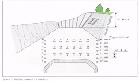 Accurate Tendering