Заглавная страница Избранные статьи Случайная статья Познавательные статьи Новые добавления Обратная связь КАТЕГОРИИ: ТОП 10 на сайте Приготовление дезинфицирующих растворов различной концентрацииТехника нижней прямой подачи мяча. Франко-прусская война (причины и последствия) Организация работы процедурного кабинета Смысловое и механическое запоминание, их место и роль в усвоении знаний Коммуникативные барьеры и пути их преодоления Обработка изделий медицинского назначения многократного применения Образцы текста публицистического стиля Четыре типа изменения баланса Задачи с ответами для Всероссийской олимпиады по праву 
Мы поможем в написании ваших работ! ЗНАЕТЕ ЛИ ВЫ?
Влияние общества на человека
Приготовление дезинфицирующих растворов различной концентрации Практические работы по географии для 6 класса Организация работы процедурного кабинета Изменения в неживой природе осенью Уборка процедурного кабинета Сольфеджио. Все правила по сольфеджио Балочные системы. Определение реакций опор и моментов защемления |
Recommended battery tester: bm-210 or battery MATE or equivalent
TROUBLESHOOTING
19-2 BATTERY/CHARGING SYSTEM
SYSTEM LOCATION
REGULATOR/RECTIFIER
BATTERY
MAIN FUSE (30 A)
ALTERNATOR
SYSTEM DIAGRAM
MAIN FUSE (30 A)
ALTERNATOR
Y: Yellow
G: Green
R: Red
W: White
19-3 BATTERY/CHARGING SYSTEM
BATTERY
REMOVAL/INSTALLATION
Connect the positive cable first and then the negative cable.
Remove the left side cover (page 2-3). Turn the ignition switch OFF.
Disconnect the negative (–) cable [1] first and then the positive (+) cable [2].
Remove the bolt [3], battery holder plate [4] and battery [5].
Install the battery in the reverse order of removal.
TORQUE:
Battery holder plate bolt:
7.0 N·m (0.7 kgf·m, 5.2 lbf·ft) • Install the battery holder plate by aligning its hook with the slit of the battery case. • For digital clock setting procedure (page 20-7).
Align
[5]
VOLTAGE INSPECTION
Measure the battery voltage using a commercially available digital multimeter.
VOLTAGE (20°C/68°F):
Fully charged: 13.0 – 13.2 V Under charged: Below 12.3 V
If the battery voltage is below 12.3 V, charge the battery.
BATTERY TESTING
Refer to the instructions that are appropriate to the battery testing equipment available to you.
TOOL:
Battery tester BM-210 or BATTERY MATE or equivalent
CHARGING SYSTEM INSPECTION
CURRENT LEAKAGE INSPECTION
• When measuring current using a tester, set it to a high range, and then bring the range down to an appropriate level. Current flow higher than the range
SPECIFIED CURRENT LEAKAGE: 0.34 mA max.
19-4 BATTERY/CHARGING SYSTEM
• To prevent a short, make absolutely certain which are the positive (+) and negative (–) terminal or cable.
• Do not disconnect the battery or any cable in the charging system without first turning the ignition
With the headlight high beam, measure the voltage on
the multimeter when the engine runs at 5,000 min-1 (rpm).
STANDARD:
Measured BV < Measured CV < 15.5 V • BV = Battery Voltage • CV = Charging Voltage
ALTERNATOR CHARGING COIL
INSPECTION
Remove the left side cover (page 2-3). Disconnect the alternator 3P connector [1].
Measure the resistance between the Yellow wire terminals of the alternator side connector.
STANDARD: 0.1 – 1.0 Ω (20°C/68°F)
Check for continuity between each wire terminal of the alternator/stator side connector and ground.
There should be no continuity.
Replace the alternator stator if the resistance is out of specification, or if any wire has continuity to ground.
19-5 BATTERY/CHARGING SYSTEM
REGULATOR/RECTIFIER
REMOVAL/INSTALLATION
Remove the bolts [2] and regulator/rectifier [3] from the reserve tank stay.
Install the regulator/rectifier in the reverse order of removal.
[1]
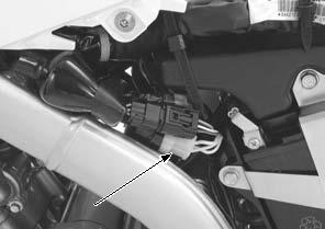
SYSTEM INSPECTION
Remove the right fuel tank shroud (page 2-4).
Turn the ignition switch OFF. Disconnect the regulator/rectifier 5P connector [1], and check it for loose contacts or corroded terminals.
If the charging voltage reading (page 19-5) is out of the specification, check the following at the wire harness side connector [1]:
If all components of the charging system are normal and there are no loose connections at the regulator/ rectifier connector, replace the regulator/rectifier unit.
[1]
[1]
19-6 LIGHTS/METERS/SWITCHES
SERVICE INFORMATION···························20-2
SYSTEM LOCATION···································20-2
HEADLIGHT ················································20-3
POSITION LIGHT ········································20-3
TURN SIGNAL LIGHT·································20-4
BRAKE/TAILLIGHT·····································20-5
SPEEDOMETER··········································20-5 VS SENSOR ················································20-8
HIGH COOLANT TEMPERATURE INDICATOR ·················································20-9
IGNITION SWITCH····································20-10
HANDLEBAR SWITCH·····························20-11
BRAKE LIGHT SWITCH ···························20-12
NEUTRAL SWITCH ··································20-12
SIDESTAND SWITCH·······························20-13
CLUTCH SWITCH·····································20-14
FUEL GAUGE/FUEL LEVEL SENSOR····················································20-14
HORN ························································20-15 TURN SIGNAL RELAY ·····························20-15
20-1 LIGHTS/METERS/SWITCHES
SERVICE INFORMATION
GENERAL
• Note the following when replacing the halogen headlight bulb. – Wear clean gloves while replacing the bulb. Do not put fingerprints on the headlight bulb, as they may create hot spots on the bulb and cause it to fail. – If you touch the bulb with your bare hands, clean it with a cloth moistened with alcohol to prevent its early failure. • Be sure to install the dust cover after replacing the headlight bulb. • A halogen headlight bulb becomes very hot while the headlight is ON, and remains hot for a while after it is turned OFF. Be sure to let it cool down before servicing. • Check the battery condition before performing any inspection that requires proper battery voltage. • A continuity test can be made with the switches installed on the motorcycle. • The following color codes are used throughout this section.
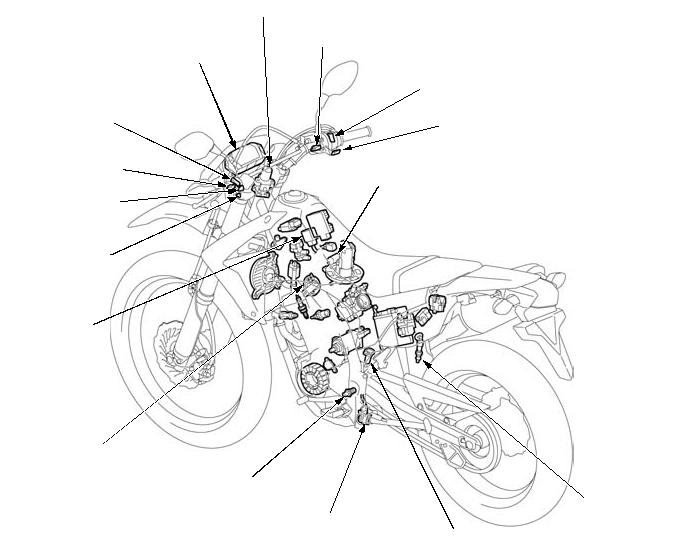
SYSTEM LOCATION
DIMMER SWITCH
CLUTCH SWITCH
HORN SWITCH
TURN SIGNAL
SWITCH
TURN SIGNAL
RELAY
HORN
IGNITION SWITCH
FRONT BRAKE LIGHT SWITCH
SPEEDOMETER
ENGINE STOP SWITCH
STARTER SWITCH
FUEL LEVEL SENSOR
NEUTRAL SWITCH
SIDESTAND SWITCH
VS SENSOR
REAR BRAKE LIGHT SWITCH
20-2 LIGHTS/METERS/SWITCHES
HEADLIGHT
BULB REMOVAL/INSTALLATION
Remove the headlight cowl (page 2-5).
TORQUE:
Headlight unit mounting screw: 1.2 N·m (0.1 kgf·m, 0.9 lbf·ft)
[1]
[2]
POSITION LIGHT
BULB REMOVAL/INSTALLATION
Remove the headlight cowl (page 2-5).
Pull out the bulb socket [1] from the headlight case.
Remove the bulb [2] from the socket.
Installation is in the reverse order of removal.
[2]
[1]
20-3 LIGHTS/METERS/SWITCHES
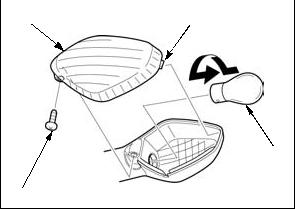
TURN SIGNAL LIGHT
BULB REMOVAL/INSTALLATION
[4]
[1]
FRONT TURN SIGNAL UNIT REMOVAL/INSTALLATION
Remove the headlight cowl (page 2-5).
Disconnect the front turn signal 2P connector [1].
– Right side: Light blue – Left side: Orange
Release the wire from the wire band [2]. Left side only: Release the wire from the wire band [3].
Remove the nut [4] and front turn signal unit [5]. Installation is in the reverse order of removal.
TORQUE:
Turn signal unit mounting nut: 21 N·m (2.1 kgf·m, 15 lbf·ft)
Align the flats of the turn signal unit and speedometer stay.
|
||||||||||||||||||||||||||||||||||||||||||||||||||||||||||||||||||||||||||||||||||||||||||||||||||||||||||||||||||||||||||||||||||||||||||||||||||||||||||||||||||||||||||||||||||||||||||||||||||||||||||||||||||||||||||||||||||||||||||||||||||||||||||||||||||||||||||||||||||||||||||||||||||||||||||||||||||||||||||||||||||||||||||||||||||||||||||||||||||||||||||||||||||||||||||||||||||||||||||||||||||||||||||||||||||||||||||||||||||||||||||||||||||||||||||||||||||||||||||||||||||||||||||||||||||||||||||||||||||||||||||||||||||||||||||||||||||||||||||||||||
|
|
Последнее изменение этой страницы: 2016-04-08; просмотров: 590; Нарушение авторского права страницы; Мы поможем в написании вашей работы! infopedia.su Все материалы представленные на сайте исключительно с целью ознакомления читателями и не преследуют коммерческих целей или нарушение авторских прав. Обратная связь - 3.145.131.238 (0.145 с.) |