Заглавная страница Избранные статьи Случайная статья Познавательные статьи Новые добавления Обратная связь КАТЕГОРИИ: ТОП 10 на сайте Приготовление дезинфицирующих растворов различной концентрацииТехника нижней прямой подачи мяча. Франко-прусская война (причины и последствия) Организация работы процедурного кабинета Смысловое и механическое запоминание, их место и роль в усвоении знаний Коммуникативные барьеры и пути их преодоления Обработка изделий медицинского назначения многократного применения Образцы текста публицистического стиля Четыре типа изменения баланса Задачи с ответами для Всероссийской олимпиады по праву 
Мы поможем в написании ваших работ! ЗНАЕТЕ ЛИ ВЫ?
Влияние общества на человека
Приготовление дезинфицирующих растворов различной концентрации Практические работы по географии для 6 класса Организация работы процедурного кабинета Изменения в неживой природе осенью Уборка процедурного кабинета Сольфеджио. Все правила по сольфеджио Балочные системы. Определение реакций опор и моментов защемления |
Clutch lever too hard to pull in
• Damaged, kinked or dirty clutch cable • Improperly routed clutch cable • Damaged clutch lifter mechanism • Faulty clutch lifter plate bearing
Clutch will not disengage or motorcycle creeps with clutch disengaged • Excessive clutch lever freeplay • Clutch plate warped • Engine oil level too high, improper oil viscosity or additive used • Loose clutch center lock nut
Clutch slips • Clutch lifter sticking • Worn clutch discs • Weak clutch springs • No clutch lever freeplay • Engine oil level too low or oil additive used
Hard to shift • Misadjusted clutch cable • Damaged or bent shift fork • Bent shift fork shaft • Incorrect engine oil viscosity • Bent or damaged gearshift spindle • Damaged shift drum stopper plate • Damaged shift drum guide grooves (page 14-11)
Transmission jumps out of gear • Worn shift drum stopper arm • Worn or broken gearshift spindle return spring • Bent shift fork shaft • Worn or damaged shift drum stopper plate • Damaged shift drum guide grooves (page 14-11) • Worn gear dogs or dog holes (page 14-11)
Gearshift pedal will not return • Weak or broken gearshift spindle return spring • Bent gearshift spindle
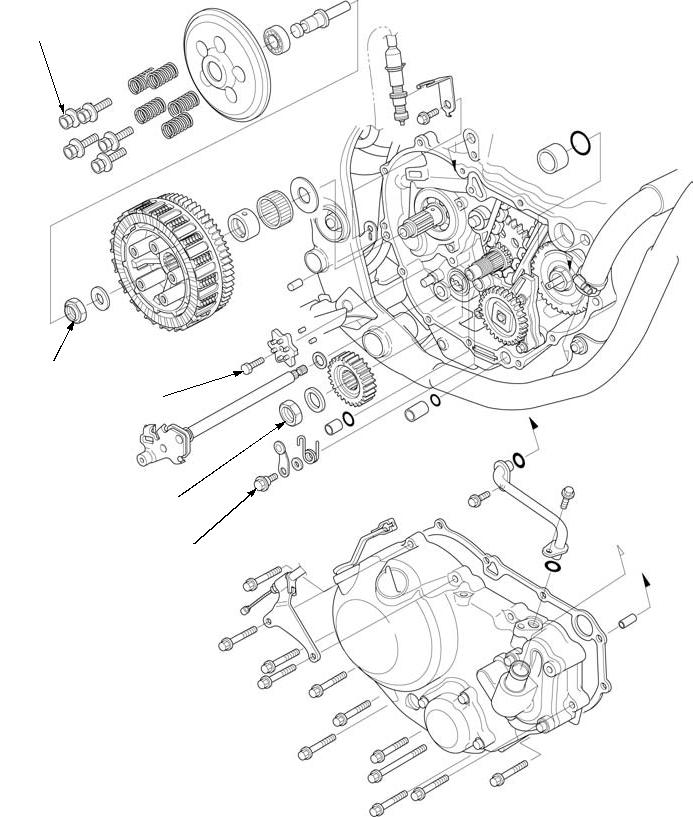
12-2 CLUTCH/GEARSHIFT LINKAGE
COMPONENT LOCATION
12 N·m (1.2 kgf·m, 9 lbf·ft)
108 N·m (11.0 kgf·m, 80 lbf·ft)
10 N·m (1.0 kgf·m, 7 lbf·ft)
108 N·m (11.0 kgf·m, 80 lbf·ft)
10 N·m (1.0 kgf·m, 7 lbf·ft)
12-3 CLUTCH/GEARSHIFT LINKAGE
RIGHT CRANKCASE COVER
REMOVAL
Remove the following:
– Water pipe (page 9-13) – Frame guard (page 2-6) – Brake pedal (page 18-12)
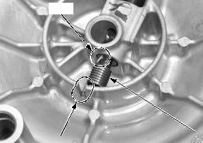
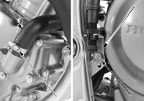
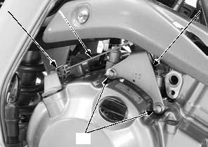
Remove the bolts [1] and clutch cable guide [2], then disconnect the clutch cable [3] from the clutch lifter arm [4].
[1]
Be careful not to let the return spring fall into the crankcase.
Loosen the water hose band screw [1] and disconnect the water hose [2].
Remove the bolt [3] and rear brake light switch holder [4].
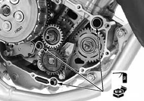
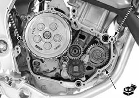
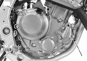
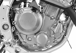
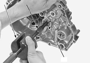
Loosen the right crankcase cover bolts [1] in a crisscross pattern in 2 or 3 steps and remove the bolts.
Remove the right crankcase cover [2] while turning the clutch lifter arm [3] counterclockwise to disengage the lifter arm spindle from the lifter piece.
[3]
[3]
12-4 CLUTCH/GEARSHIFT LINKAGE
Remove the collars [1] and O-rings [2].
[1]/[2]
DISASSEMBLY
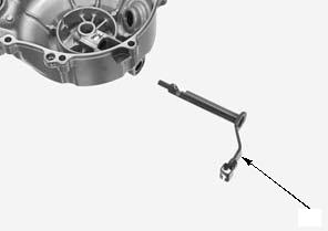
Remove the return spring [1] from the right crankcase cover.
[1]
Remove the clutch lifter arm [1] from the right crankcase cover.
[1]
INSPECTION
Inspect the following parts for scratch, damage, abnormal wear and deformation. Replace if necessary.
– Oil seal – Clutch lifter arm needle bearing – Clutch lifter arm – Return spring – Crankshaft bearing
12-5 CLUTCH/GEARSHIFT LINKAGE
BEARING REPLACEMENT
[1]
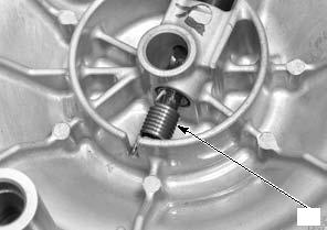
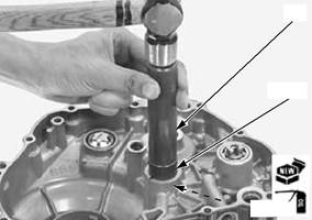
Drive in a new crankshaft bearing [1] into the right crankcase cover with the marked side facing up until it is fully seated using the special tools.
After installation, apply engine oil to the bearing.
CLUTCH LIFTER ARM NEEDLE BEARING
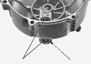
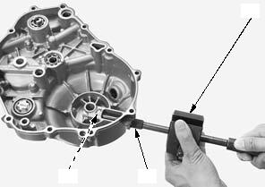
Remove the oil seal [1] from the right crankcase cover.
Remove the clutch lifter arm needle bearings [2] using the special tools.
[2]
[3]/[4]
[4]
[2] [3]
12-6 CLUTCH/GEARSHIFT LINKAGE
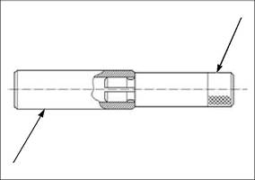
Install the bearing remover head [1] to the pilot collar [2] as shown.
[1]
[2]
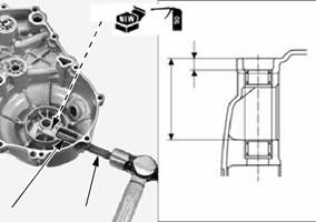
Drive in a new clutch lifter arm needle bearings [1] until the specified depth, using the special tools as shown.
After installation, apply engine oil to the bearing.
[1]
(0.26 – 0.30 in)
Install a new oil seal [1] to the right crankcase cover as shown.
ASSEMBLY
Apply grease to the clutch lifter arm oil seal lips [1]. Apply molybdenum oil solution to the clutch lifter arm [2] sliding surface.
Install the clutch lifter arm to the right crankcase cover.
0.5 – 1.0 mm
(0.02 – 0.04 in)
12-7 CLUTCH/GEARSHIFT LINKAGE
Be careful not to damage the mating surfaces.
Be careful not to let the return spring fall into the crankcase.
Install the return spring [1] to the right crankcase cover by aligning the spring short end with the hole of the clutch lifter arm and long end with the groove of the right crankcase cover.
INSTALLATION
Clean any gasket material from the mating surfaces of the right crankcase and cover.
Apply engine oil to new O-rings [1]. Install the collars [2] and O-rings.
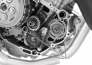
Install the dowel pin A [1], dowel pin B [2] and a new gasket [3].
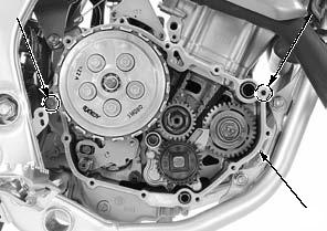
Install the right crankcase cover [1] while turning the clutch lifter arm [2] clockwise to engage the lifter arm spindle groove with the lifter piece flange.
Install and tighten the bolts [3] in a crisscross pattern in 2 or 3 steps.
Align
[1]
[3]
[2]
12-8 CLUTCH/GEARSHIFT LINKAGE
Connect the water hose [1] and tighten the water hose band screw [2] (page 9-7).
Install the rear brake light switch holder [3] and tighten the bolt [4].
Connect the clutch cable [1] to the clutch lifter arm [2].
Install the clutch cable guide [3] and bolts [4].
Tighten the bolts securely.
Install the following:
– Brake pedal (page 18-12) – Frame guard (page 2-6) – Water pipe (page 9-13)
Adjust the clutch lever freeplay (page 3-18).
Fill the engine with the recommended engine oil (page 3-9).
Fill the recommended coolant and bleed the air (page 9-5).
CLUTCH
REMOVAL
Remove the right crankcase cover (page 12-4).
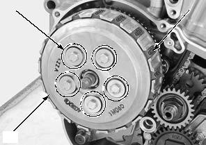
Loosen the clutch lifter plate bolts [1] in a crisscross pattern in 2 or 3 steps.
Remove the clutch lifter plate bolts and clutch springs [2].
Remove the clutch lifter plate [3]. Remove the clutch discs [4] and plates [5].
Remove the clutch lifter piece [1], judder spring [2] and spring seat [3].
[4]
[3]
[2]/[3]
[1]
12-9 CLUTCH/GEARSHIFT LINKAGE
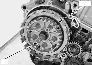
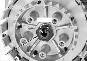
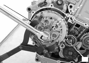
Unstake the clutch center lock nut [1].
Hold the clutch center [1] with the special tool and loosen the clutch center lock nut [2].
Remove the clutch center lock nut and washer [4].
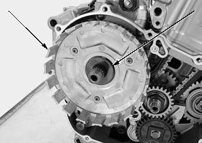
Remove the washer [1] and clutch outer [2].
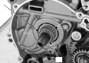
Remove the needle bearing [1], clutch outer guide [2] and washer [3] from the mainshaft.
Unstake
[1]
[1]
[2]
12-10 CLUTCH/GEARSHIFT LINKAGE
INSPECTION
Inspect the following parts for scratch, damage, abnormal wear and deformation. Replace if necessary.
– Clutch lifter bearing – Clutch springs – Clutch center – Clutch discs/plates – Clutch outer – Clutch outer guide/needle bearing – Mainshaft
Measure each part according to CLUTCH/GEARSHIFT LINKAGE SPECIFICATIONS (page 1-7).
Replace any part if it is out of service limit.
• Replace the clutch springs as a set. • Replace the clutch discs and plates as a set.
|
|||||||||||||||||||||||||||||||||||||||||||||||||||||||||||||||||||||||||||||||||||||||||||||||||||||||||||||||||||||||||||||||||||||||||||||||||||||||||||||||||||||||||||||||||||||||||||||||||||||||||||||||||||||||||||||||||||||||||||||||||||||||||||||||||||||||||||||||||||||
|
|
Последнее изменение этой страницы: 2016-04-08; просмотров: 344; Нарушение авторского права страницы; Мы поможем в написании вашей работы! infopedia.su Все материалы представленные на сайте исключительно с целью ознакомления читателями и не преследуют коммерческих целей или нарушение авторских прав. Обратная связь - 18.189.3.137 (0.101 с.) |


 [1]
[1] 


 6.5 – 7.5 mm
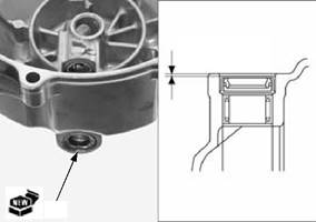
 [1]
[1]