Заглавная страница Избранные статьи Случайная статья Познавательные статьи Новые добавления Обратная связь КАТЕГОРИИ: ТОП 10 на сайте Приготовление дезинфицирующих растворов различной концентрацииТехника нижней прямой подачи мяча. Франко-прусская война (причины и последствия) Организация работы процедурного кабинета Смысловое и механическое запоминание, их место и роль в усвоении знаний Коммуникативные барьеры и пути их преодоления Обработка изделий медицинского назначения многократного применения Образцы текста публицистического стиля Четыре типа изменения баланса Задачи с ответами для Всероссийской олимпиады по праву 
Мы поможем в написании ваших работ! ЗНАЕТЕ ЛИ ВЫ?
Влияние общества на человека
Приготовление дезинфицирующих растворов различной концентрации Практические работы по географии для 6 класса Организация работы процедурного кабинета Изменения в неживой природе осенью Уборка процедурного кабинета Сольфеджио. Все правила по сольфеджио Балочные системы. Определение реакций опор и моментов защемления |
Service limit: 0. 10 mm (0. 004 in)
When the service limit is exceeded, measure the camshaft journal O.D. and camshaft journal area I.D. of cylinder head and camshaft holders, then compare the measurement with the standard value (page 1-6).
• Replace the cylinder head and camshaft holders as a set if the difference from the standard value is larger than that of the camshaft.
• Replace the camshaft if the difference from the standard value is larger than that of the cylinder head and camshaft holders.
10-8 CYLINDER HEAD/VALVES
INSTALLATION
Be careful not to Rotate the crankshaft counterclockwise, and align the jam the cam chain "T" mark [1] on the flywheel with the index notch [2] on and timing sprocket the left crankcase cover.
on the crankshaft when rotating the crankshaft.
Each camshaft has an identification mark.
• "IN" mark [1]: intake camshaft • "EX" mark [2]: exhaust camshaft
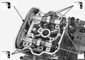
Apply molybdenum oil solution to the camshaft [1] lobes and journal surfaces.
Apply engine oil to the cam chain [2] whole surface.
Install the camshafts into the cylinder head while installing cam chain onto the cam sprockets.
Install the camshaft with its lobes facing up.
[1]
[2]
[2]
[2]
[1]
[1]
[1]
10-9 CYLINDER HEAD/VALVES
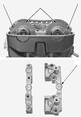
Align the outside index line ("IN" [1] and "EX" [2] marks) on the cam sprockets with the cylinder head top surface as shown.
• Check that the punch marks [3] of the cam sprockets is facing up as shown.
Install the camshaft holders.
Note the correct locations with the identification marks [1] as shown.
– "R" mark: right camshaft holder – "L" mark: left camshaft holder – "IN" mark: intake side – "EX" mark: exhaust side
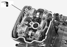
Apply engine oil to the camshaft holder mounting bolt [1] threads and seating surface.
Install and tighten the camshaft holder mounting bolts to the specified torque.
TORQUE:12 N·m (1.2 kgf·m, 9 lbf·ft)
From inside to outside, tighten the bolts in a crisscross pattern in several steps.
[1]
Be careful not to let Install the cam chain guide B [1] and bolts [2].
the crankcase.
[2]
10-10 CYLINDER HEAD/VALVES
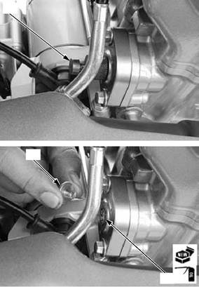
Remove the tensioner stopper [1] from the cam chain tensioner lifter.
Apply engine oil to a new O-ring [1] and install it to the cam chain tensioner lifter.
Install and tighten the cam chain tensioner lifter plug [2] to the specified torque.
TORQUE:4.2 N·m (0.4 kgf·m, 3.1 lbf·ft)
Inspect the valve clearance (page 3-6). Install the cylinder head cover (page 10-5).
ROCKER ARM
• The rocker arm can be serviced with the engine installed in the frame.
• The intake and exhaust rocker arm service procedures are the same.
REMOVAL/INSTALLATION
Remove the camshafts (page 10-6).
Remove the bolt [1] and sealing washer [2].
[1]
[1]
[1]/[2]
10-11 CYLINDER HEAD/VALVES
Remove the rocker arm shaft [1] using a 6 mm bolt [2] while holding the rocker arm [3].
Remove the rocker arm.
Apply molybdenum oil solution to the rocker arm inner surface, roller surface, slipper surface and rocker arm shaft outer surface.
Install the rocker arm and rocker arm shaft.
• The rocker arms are identified by the stamped marks: – "IN": Intake rocker arm [4] – "EX": Exhaust rocker arm [5]
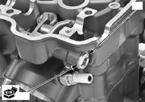
Install a new sealing washer [1] and bolt [2]. Install the camshafts (page 10-9).
INSPECTION
Inspect the following parts for damage, abnormal wear, deformation, burning or clogs in oil passages.
– Rocker arm – Rocker arm shaft
Measure each part and clearance according to CYLINDER HEAD/VALVES SPECIFICATIONS (page 1-6).
Replace any part if it is out of service limit.
[2]
10-12 CYLINDER HEAD/VALVES
CYLINDER HEAD
Be careful not to let the cylinder head bolts and nuts fall into the crankcase.
REMOVAL
Remove the following:
– Engine (page 15-4) – Camshaft (page 10-6)
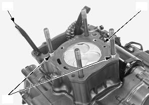
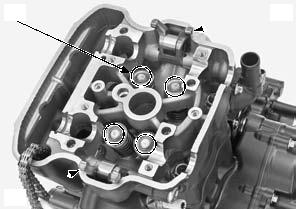
Remove the cylinder head bolts [1], nuts [2], washers [3] and cylinder head [4].
• Attach a piece of wire to the cam chain to prevent it from falling into the crankcase.
• Do not tap the cylinder head too hard and do not damage the mating surface with a screwdriver.
Remove the following:
– Dowel pins [1] – Gasket [2] – Cam chain guide A [3]
[1]
[3]
[1]
[2]/[3]
[4]
[2]
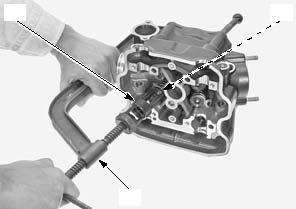
To prevent loss of tension, do not compress the valve springs more than necessary to remove the cotters.
Mark all parts during disassembly so they can be installed in their original locations.
DISASSEMBLY
Remove the following:
– Spark plug (page 3-5) – O2 sensor (page 4-47) – Rocker arm (page 10-11)
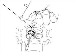
Remove the valve spring cotters [1] using the special tools.
Remove the following:
– Spring retainer – Outer/inner valve springs – Valve – Stem seal – Spring seat
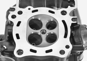
INSPECTION
Inspect the following parts for damage, abnormal wear, deformation, burning or clogs in oil passages.
– Cylinder head – Inner/outer valve springs – Valves – Valve guides – Cam chain guide A
Measure each part and clearance according to CYLINDER HEAD/VALVES SPECIFICATIONS (page 1-6).
Replace any part if it is out of service limit.
[3]
[2]
[1]
10-13 CYLINDER HEAD/VALVES
VALVE GUIDE REPLACEMENT
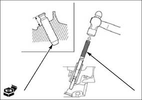
Support the cylinder head and drive out the valve guides from the combustion chamber side of the cylinder head.
TOOL:
[1] Valve guide driver 07HMD-ML00101
While the cylinder head is still heated, take off a new valve guides [1] from the freezer.
Adjust the valve guide driver to the valve guide height and drive in the valve guide from the camshaft side.
SPECIFIED HEIGHT:
IN/EX: 13.8 – 14.0 mm (0.54 – 0.55 in)
Let the cylinder head cool to room temperature.
[1]
• Use cutting oil on the reamer during this operation. • Take care not to tilt or lean the reamer in the guide while reaming. Otherwise, the valves may be installed slanted, causing oil leakage from the stem seal and improper valve seat contact. This may prevent valve seat refacing
• Insert the reamer from the combustion chamber side of the head and always rotate the reamer clockwise.
Clean the cylinder head thoroughly to remove any metal particles after reaming and reface the valve seat (page 10-15).
[1]
[2]
10-14 CYLINDER HEAD/VALVES
|
|||||||||||||||||||||||||||||||||||||||||||||||||||||||||||||||||||||||||||||||||||||||||||
|
|
Последнее изменение этой страницы: 2016-04-08; просмотров: 320; Нарушение авторского права страницы; Мы поможем в написании вашей работы! infopedia.su Все материалы представленные на сайте исключительно с целью ознакомления читателями и не преследуют коммерческих целей или нарушение авторских прав. Обратная связь - 18.226.4.239 (0.051 с.) |


 [2]
[2]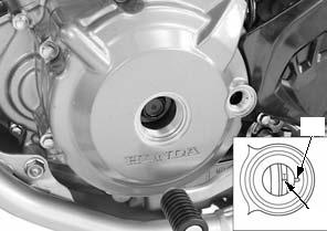
 [2]
[2]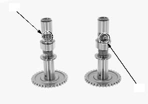


 [1]
[1]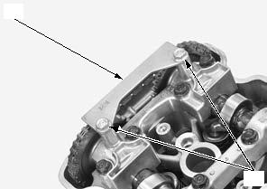 the cam chain Tighten the cam chain guide bolts securely. [1] guide bolts fall into

 [2]
[2]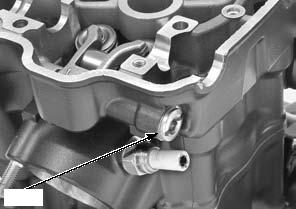


 [1]
[1]