Заглавная страница Избранные статьи Случайная статья Познавательные статьи Новые добавления Обратная связь КАТЕГОРИИ: ТОП 10 на сайте Приготовление дезинфицирующих растворов различной концентрацииТехника нижней прямой подачи мяча. Франко-прусская война (причины и последствия) Организация работы процедурного кабинета Смысловое и механическое запоминание, их место и роль в усвоении знаний Коммуникативные барьеры и пути их преодоления Обработка изделий медицинского назначения многократного применения Образцы текста публицистического стиля Четыре типа изменения баланса Задачи с ответами для Всероссийской олимпиады по праву 
Мы поможем в написании ваших работ! ЗНАЕТЕ ЛИ ВЫ?
Влияние общества на человека
Приготовление дезинфицирующих растворов различной концентрации Практические работы по географии для 6 класса Организация работы процедурного кабинета Изменения в неживой природе осенью Уборка процедурного кабинета Сольфеджио. Все правила по сольфеджио Балочные системы. Определение реакций опор и моментов защемления |
FRAME/BODY PANELS/EXHAUST SYSTEM
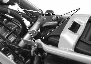
Remove the rear lower fender mounting bolt [1].
Remove the bolts [1], helmet holder [2] and rear lower fender [3].
Use a drill or an equivalent tool when removing the helmet holder mounting bolts.
Installation is in the reverse order of removal.
• Replace the helmet holder mounting bolts with new ones.
[1]
2-10 FRAME/BODY PANELS/EXHAUST SYSTEM
EXHAUST PIPE/MUFFLER
REMOVAL/INSTALLATION
Remove the following:
– Seat (page 2-3) – Right side cover (page 2-3)
Remove the exhaust pipe/muffler as following illustration.
Installation is in the reverse order of removal.
MUFFLER PROTECTOR
MUFFLER
STUD BOLT REPLACEMENT
Remove the exhaust pipe (page 2-11).
Thread two nuts onto the stud bolt and tighten them together, and use a wrench on them to turn the stud bolt out.
Install and tighten new stud bolts to the specified torque.
TORQUE: 9.0 N·m (0.9 kgf·m, 6.6 lbf·ft)
After installation, check that the length from the bolt head to the cylinder head surface is within specification.
22.0 ± 0.5 mm
(0.87 ± 0.02 in)
2-11 FRAME/BODY PANELS/EXHAUST SYSTEM
SUB-FRAME
REMOVAL/INSTALLATION
Remove the following:
– Seat (page 2-3) – Side covers (page 2-3) – Muffler (page 2-11) – Fuel tank (page 7-8) – Battery (page 19-4)
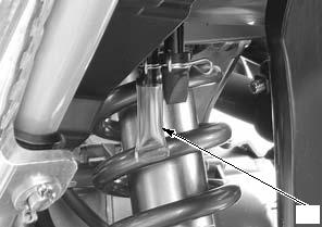
Remove the bolt [1] and reservoir [2].
Disconnect the PAIR air suction hose [3] and crankcase breather hose [4] from the air cleaner housing.
Remove the wire bands [1].
Remove the following from the air cleaner housing.
– Starter relay switch [2] – Fuse box [3] – Relay box [4] – Wire clips [5]
Open the harness band [1] and release the wires.
Disconnect the battery case drain hose [2].
[3]
[5] [2]
Release the wire bands [1].
[1]
Disconnect the brake/taillight 6P (Black) connector [2].
[2]
2-12 FRAME/BODY PANELS/EXHAUST SYSTEM
Loosen the air cleaner connecting hose band screw [1].
Remove the sub-frame lower mounting bolts [1].
Remove the sub-frame upper mounting nuts [1] and bolts [2].
Pull the sub-frame assembly rearward, then disconnect the air cleaner connecting hose from the throttle body. Remove the sub-frame.
Install the sub-frame in position, connect the air cleaner connecting hose to the throttle body.
Tighten the band screw to the specified torque.
TORQUE: 1.5 N·m (0.2 kgf·m, 1.1 lbf·ft)
Loosely install all the mounting fasteners. Tighten the upper mounting nut first, then the lower bolts to the specified torque.
TORQUE:
Sub-frame upper mounting nut: 27 N·m (2.8 kgf·m, 20 lbf·ft)
Sub-frame lower mounting bolt: 27 N·m (2.8 kgf·m, 20 lbf·ft)
Install the removed parts in the reverse order of removal.
TORQUE:
Rear master cylinder reservoir mounting bolt: 10 N·m (1.0 kgf·m, 7 lbf·ft)
[1]
[1]
2-13 FRAME/BODY PANELS/EXHAUST SYSTEM
SIDESTAND
REMOVAL/INSTALLATION
Remove the sidestand switch (page 20-14). Remove the return spring [1] and sub spring [2].
Remove the pivot lock nut [3], pivot bolt [4] and sidestand [5].
Apply grease to the sidestand pivot bolt sliding surface. Install the sidestand and pivot bolt, then tighten it to the specified torque.
TORQUE: 10 N·m (1.0 kgf·m, 7 lbf·ft)
Turn the pivot bolt counterclockwise about 45° – 90°.
Install the pivot lock nut and tighten it to the specified torque while holding the pivot bolt.
TORQUE: 30 N·m (3.1 kgf·m, 22 lbf·ft)
Install the return spring and sub spring as shown. Install the sidestand switch (page 20-14).
[5]
[2]
2-14 MAINTENANCE
SERVICE INFORMATION·····························3-2 DRIVE CHAIN ·············································3-12
MAINTENANCE SCHEDULE························3-2 DRIVE CHAIN SLIDER ·······························3-14
FUEL LINE·····················································3-3 BRAKE FLUID ············································3-15
THROTTLE OPERATION······························3-3 BRAKE PADS WEAR ·································3-16
AIR CLEANER···············································3-4 BRAKE SYSTEM ········································3-17
CRANKCASE BREATHER ···························3-4 BRAKE LIGHT SWITCH ·····························3-17
SPARK PLUG················································3-5 HEADLIGHT AIM ········································3-18
VALVE CLEARANCE····································3-6 CLUTCH SYSTEM ······································3-18
ENGINE OIL ··················································3-9 SIDESTAND ················································3-19
ENGINE OIL FILTER···································3-10 SUSPENSION ·············································3-19
ENGINE IDLE SPEED·································3-10 NUTS, BOLTS, FASTENERS ·····················3-19
RADIATOR COOLANT ·······························3-11 WHEELS/TIRES··········································3-20
COOLING SYSTEM·····································3-11 STEERING HEAD BEARINGS ···················3-20
SECONDARY AIR SUPPLY SYSTEM········3-11
3-1 MAINTENANCE
SERVICE INFORMATION
GENERAL
• Place the motorcycle on level surface before starting any work. • Gasoline is extremely flammable and is explosive under certain conditions. • Work in a well ventilated area. Smoking or allowing flames or sparks in the work area or where the gasoline is stored can cause a fire or explosion.
• The exhaust contains poisonous carbon monoxide gas that may cause loss of consciousness and may lead to death. Run the engine in an open area or with an exhaust evacuation system in an enclosed area.
MAINTENANCE SCHEDULE
Perform the Pre-ride inspection in the Owner's Manual at each scheduled maintenance period.
I: Inspect and Clean, Adjust, Lubricate or Replace if necessary. C: Clean. R: Replace. A: Adjust. L: Lubricate.
The following items require some mechanical knowledge. Certain items (particularly those marked * and **) may require more technical information and tools. Consult a dealer.
* Should be serviced by a dealer, unless the owner has proper tools and service data and is mechanically qualified.
** In the interest of safety, we recommend these items be serviced only by a dealer.
Honda recommends that a dealer should road test your motorcycle after each periodic maintenance is carried out. NOTES: 1. At higher odometer readings, repeat at the frequency interval established here. 2. Service more frequently when riding in unusually wet or dusty areas. 3. Service more frequently when riding in rain or at full throttle. 4. Service more frequently when riding OFF-ROAD. 5. Replacement requires mechanical skill.
3-2 MAINTENANCE
FUEL LINE
INSPECTION
Remove the right fuel tank shroud (page 2-4). Check the quick connect fitting [1] for looseness.
Check the fuel feed hose [2] for deterioration, damage or leakage.
Check the quick connect fitting for dirt, and clean if necessary.
Replace the fuel pump packing if necessary (page 7-9).
THROTTLE OPERATION
Check for any deterioration or damage to the throttle cable. Check the throttle grip for smooth operation.
Check that the throttle opens and automatically closes in all steering positions.
If the throttle grip does not return properly, overhaul and lubricate the throttle grip housing.
If the throttle grip still do not return properly, replace the throttle cable.
With the engine idling, turn the handlebar all the way to the right and left to ensure that the idle speed does not change.
If idle speed increases, check the throttle grip freeplay and throttle cable connection.
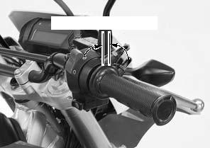
Measure the throttle grip freeplay at the throttle grip flange.
FREEPLAY: 2 – 6 mm (0.08 – 0.24 in)
Throttle grip freeplay can be adjusted at either end of the throttle cable.
Minor adjustment is made with the upper adjuster [1] at throttle housing.
Loosen the lock nut [2] and turn the adjuster.
Tighten the lock nut securely while holding the adjuster. Recheck the throttle operation.
[2]
[1]
2 – 6 mm (0.08 – 0.24 in)
[1]
[2]
3-3 MAINTENANCE
Loosen the lock nut [2] and turn the adjuster.
Tighten the lock nut to the specified torque while holding the adjuster.
TORQUE:3.0 N·m (0.3 kgf·m, 2.2 lbf·ft)
Recheck the throttle operation.
AIR CLEANER
REMOVAL/INSTALLATION
• The viscous paper element cannot be cleaned because the element contains a dust adhesive. • If the motorcycle is used in unusually wet or dusty areas, more frequent inspections are required.
Remove the right side cover (page 2-3). Remove the screws [1] and air cleaner cover [2].
Remove the air cleaner element [3] by releasing its grooves from the housing.
Inspect the air cleaner element in accordance with the maintenance schedule (page 3-2) or any time it is excessively dirt or damaged.
Install the air cleaner element in the reverse order of removal.
• After installing air cleaner element, make sure the air cleaner element grooves are secure.
• Check that the condition of the packings, replace them if necessary.
TORQUE:
Air cleaner cover screw:
1.2 N·m (0.1 kgf·m, 0.9 lbf·ft)
[2]
[1]
CRANKCASE BREATHER
Service more Check the crankcase breather hose [1] for deterioration, frequently when damage or loose connection. Make sure that the hoses
ridden in rain, at full are not kinked, pinched or cracked.
throttle, or after the Replace the crankcase breather hose if necessary. motorcycle is
washed or overturned.
[1]
[1]
[3]
3-4 MAINTENANCE
Service if the deposits level can be seen in the air cleaner housing drain plug.
Check the air cleaner housing drain plug [1].
If necessary, remove the drain plug from the air cleaner and drain the deposits into a suitable container.
Reinstall the drain plug securely.
[1]
SPARK PLUG
REMOVAL/INSTALLATION
Disconnect the spark plug cap [1].
[1]
Clean around the spark plug base with compressed air before removing the spark plug, and be sure that no debris is allowed to enter into the combustion chamber.
Inspect or replace the spark plug as described in the maintenance schedule (page 3-2).
Install and hand tighten the spark plug to the cylinder head, then tighten the spark plug to the specified torque using a spark plug wrench.
TORQUE:16 N·m (1.6 kgf·m, 12 lbf·ft)
Connect the spark plug cap securely.
[1]
INSPECTION
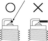
This motorcycle's spark plug is equipped with an iridium center electrode. Replace the spark plug if the electrodes are contaminated.
Check the following and replace if necessary (recommended spark plug: page 3-6).
• Insulator [1] for damage • Center electrode [2] and side electrode [3] for wear • Burning condition, coloration
If the electrodes are contaminated with accumulated objects or dirt, replace the spark plug.
[1]
3-5 MAINTENANCE
Always use specified spark plugs on this motorcycle.
To prevent damaging the iridium center electrode, use a wire type feeler gauge to check the spark plug gap.
Do not adjust the spark plug gap. If the gap is out of specification, replace with a new one.
SPECIFIED SPARK PLUG:
NGK: SIMR8A9
VALVE CLEARANCE
INSPECTION
• Inspect and adjust the valve clearance while the engine is cold (below 35°C/95°F). • After the valve clearance inspection, check the engine idle speed (page 3-10).
• Inspection and adjustment can be done with the engine installed in the frame.
Remove the cylinder head cover (page 10-4).
Remove the timing hole cap [1] and crankshaft hole cap [2].
Rotate the crankshaft counterclockwise and align the "T" mark [1] on the flywheel with the index notch [2] on the left crankcase cover.
[1]
[2]
[2]
[1]
3-6 MAINTENANCE
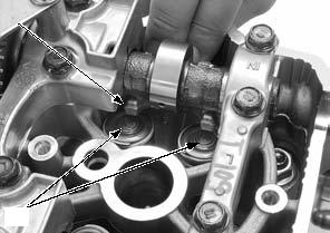
Make sure that the outside index lines ("IN" [1] and "EX" [2] marks) on the cam sprockets are flush with the cylinder head top surface and facing outward as shown.
If the "IN" and "EX" marks are facing inward, turn the
crankshaft counterclockwise one full turn (360°) and realign the "T" mark with the index notch.
Check the valve clearance by inserting a feeler gauge [1] between the rocker arm and shim.
VALVE CLEARANCE:
IN: 0.16 ± 0.03 mm (0.006 ± 0.001 in)
EX: 0.27 ± 0.03 mm (0.011 ± 0.001 in)
ADJUSTMENT
• The valve clearances can be adjusted without removing the camshafts. • The intake and exhaust valve clearance service procedures are the same.
Remove the bolt, sealing washer and rocker arm shaft (page 10-11).
Slide the rocker arm [1] and remove the shims [2].
• Do not allow the shims to fall into the crankcase. • Mark all shims to ensure correct reassembly in their original locations. • The shims can be easily removed with a tweezers or magnet.
[1]
[2]
[1]
[1]
[2]
3-7 MAINTENANCE
Sixty-nine different thickness shims are available from the thinnest 1.200 mm thickness shim to the thickest 2.900 mm thickness shim in increments of 0.025 mm.
Measure the shim [1] thickness and record it.
Calculate the new shim thickness using the equation below.
A = (B – C) + D
A: New shim thickness B: Recorded valve clearance C: Specified valve clearance D: Old shim thickness
• Make sure of the correct shim thickness by measuring the shim by micrometer.
• Inspect the valve seat if the calculated dimension is over 2.900 mm.
[1]
1.80 mm 1.825 mm 1.85 mm 1.875 mm
Install the shims in their original locations
[1]
Install the cylinder head cover (page 10-5).
Apply engine oil to new O-rings [1] and install them to each hole cap.
Apply engine oil to timing hole cap [2] and crankshaft hole cap [3] threads.
Install and tighten the timing hole cap and crankshaft hole cap to the specified torque.
TORQUE:
Timing hole cap: 6.0 N·m (0.6 kgf·m, 4.4 lbf·ft) Crankshaft hole cap: 8.0 N·m (0.8 kgf·m, 5.9 lbf·ft)
3-8 MAINTENANCE
ENGINE OIL
OIL LEVEL INSPECTION
Hold the motorcycle in an upright position.
Start the engine and let it idle for 3 – 5 minutes. Stop the engine and wait 2 – 3 minutes.
Check the oil level through the inspection window.
If the level is below the lower level line [1], remove the oil filler cap [2] and fill the crankcase with the recommended oil up to the upper level line [3].
RECOMMENDED ENGINE OIL:
Honda "4-stroke motorcycle oil" or an equivalent API classification: SG or higher (except oils labeled as energy conserving on the circular API service label)
|
||||||||||||||||||||||||||||||||||||||||||||||||||||||||||||||||||||||||||||||||||||||||||||||||||||||||||||||||||||||||||||||||||||||||||||||||||||||||||||||||||||||||||||||||||||||||||||||||||||||||||||||||||||||||||||||||||||||||||||||||||||||||||||||||||||||||||||||||||||||||||||||||||||||||||||||||||||||||||||||||||||||||||||||||||||||||||||||||||||||||||||||||||||||||||||||||||||||||||||||||||||||||||||||||||||||||||||||||||||||||||||||||||||||||||||||||||||||||||||||||||||||||||||||||||||||||||||||||||||||||||||||||||||||||||||||||||||||||||||||||||||||||||||||||||||||||||||||||||||||||||||||||||||||||||||||||||||||||||||||||||||||||||||||||||||||||||||||||||||||||||||||||||||||||||||||||||||||||||||||||||||||||||||||||||||||||||||||||||||||||||||||||||||||||||||||||||||||||||||||||||||||||||||||||||||||||||||||||||||||||||||||||||||||||||||||||||||||||||||||||||||||||||||||||||||||||||||||||||||||||||||||||||||||||||||||||||||||||||||||||||||||||||||||||||||||||||||||||||||||
|
|
Последнее изменение этой страницы: 2016-04-08; просмотров: 270; Нарушение авторского права страницы; Мы поможем в написании вашей работы! infopedia.su Все материалы представленные на сайте исключительно с целью ознакомления читателями и не преследуют коммерческих целей или нарушение авторских прав. Обратная связь - 3.147.205.154 (0.626 с.) |


 [1]/[2]


 [2]
[2]


 [1]
[1]