Заглавная страница Избранные статьи Случайная статья Познавательные статьи Новые добавления Обратная связь КАТЕГОРИИ: ТОП 10 на сайте Приготовление дезинфицирующих растворов различной концентрацииТехника нижней прямой подачи мяча. Франко-прусская война (причины и последствия) Организация работы процедурного кабинета Смысловое и механическое запоминание, их место и роль в усвоении знаний Коммуникативные барьеры и пути их преодоления Обработка изделий медицинского назначения многократного применения Образцы текста публицистического стиля Четыре типа изменения баланса Задачи с ответами для Всероссийской олимпиады по праву 
Мы поможем в написании ваших работ! ЗНАЕТЕ ЛИ ВЫ?
Влияние общества на человека
Приготовление дезинфицирующих растворов различной концентрации Практические работы по географии для 6 класса Организация работы процедурного кабинета Изменения в неживой природе осенью Уборка процедурного кабинета Сольфеджио. Все правила по сольфеджио Балочные системы. Определение реакций опор и моментов защемления |
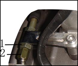
Free travel of clutch: 10-20mm
Please adjust free travel of clutch in the following way: (1) Loosen mandrill to lock nut1 (2) Twist in or out the mandril2 to adjust free travel of front brake handle, after adjusting free travel to 10-20mm. (3) Install mandrill tight and lock nut1.
Front/Rear Suspension System Front suspension Grasp the front brake handle and compress upward and downward the front shock absorber to check its actuator. Check if the front shock absorber leaks oil and if the components are loosened.
Rear suspension
Check if components on the rear shock absorber are loosened or injured. Lift and support the rear wheel and swing the wheel to check if engine suspension bushing is loosened. Bolt/Nut/Fastening Part Inspect bolts, nuts and fastening parts at every part of the motorcycle for looseness.
Wheel Rim/Tyre Check if there is crack, nails and similar sharp objects, and other injuries on the tyres.
Inspect pneumatic pressure of tyres.
* Attention
Specified air pressure Unit: Kpa
Check if lock nut of front shaft is loosened. Check if lock nut of rear shaft is loosened. If loosened, tighten it to specified torque. Torsion force: Front shaft 100-113NЎ¤m
Steering Stem Bearing and Handle Fixation Move the left and right handle and check if lead wires disturb it. Rotate front wheel and confirm handle can move smoothly. If the handle does not move smoothly and is loosened, check steering stem bearing. Check and Maintenance of Body Front liquid brake block
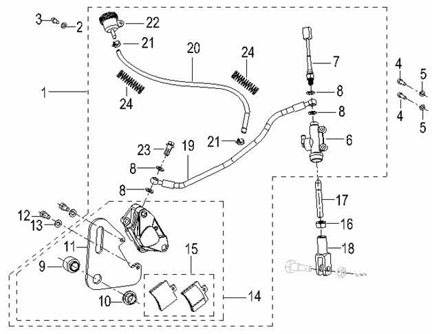
ўЕ Inner hexagon screw M8*35 ўЖ Gasket 8 ўЗ Front liquid brake block units ўИ Brake cylinder units ўЙ Brake shoe units ўК Sealing gasket ўЛ Erection bolt in oil tube ўМ Brake house units ўН Oil pump units ўО Handle ўП Thin nut M6 ўР Handle screw ўС Fixed cover ўТ Bolt M6*25 ўУ Brake switch units ўФ Countersunk flat Phillips heads for exposed screws M4*12 ўХ Mandrill ўЦ Self-locking nut M6
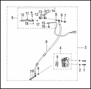
ўЕ Rear liquid brake block units ўЖ Gasket 6 ўЗ Inner hexagon screw M6*16 ўИ Inner hexagon screw M6*16 ўЙ Gasket 6 ўК Oil pump assembly ўЛ Brake switch assembly ўМ Seal ring ўН Lining I ўОLining II ўП Connecting plate ўРInner hexagon screw M8*20 ўСGasket 8 ўТ Brake cylinder B ўУ Friction plate units ўФ Nut M6 ўХ Draw bar ўЦ Draw handle ўЧ Brake hose unit ўШ Oil tube (21) Hoop (22) Oil cup units (23) Hexagon flange head tapping screw (24) Protecting spring
I Braking System Maintenance instruction--------------------1.1 Fault diagnosis-------------------------------1.2 Front hydraulic disc brake----------------- 1.3 Rear drum brake-----------------------------1.4 1.1 Maintenance Instruction Precautions on operation * Attention
* Please check braking system before driving your motorcycle.* 1.1.1 Specifications
1.1.2 Torsion force Former brake disc retaining bolt 5-10NЎ¤m Under the brake fluid before pump installation bolt 22-34NЎ¤m Liquid brake oil pump before installation bolt 5-10NЎ¤m Front wheel spindle 100-113NЎ¤m Front wheel head bolt 5-10NЎ¤m The brake disc retaining bolt 5-10NЎ¤m Liquid brake pump installation after the bolt 22-34NЎ¤m Back oil pump installing bolts liquid brake 5-10NЎ¤m Back wheel spindle 100-113NЎ¤m 1.2 Fault diagnosis 1.2.1Brake in ill performing services l Brake without adjustment well l Abrasive wear of brake shoe units and liquid brake plate l Improper installment of brake shoe units l Pollution of liquid brake plate of brake shoe units 1.2.2 Brake reaction slowly or handle is tight l Brake without adjustment well l Abrasive wear of brake shoe units and liquid brake plate Improper installment of brake shoe units 1.2.2 Brake with abnormal sound l Abrasive wear of brake shoe units and liquid brake plate l Pollution of liquid brake plate of brake shoe units 1.2.4 Braking handle/footstep is soft or light l Air in hydraulic system l Leakage of hydraulic system l Braking footstep/plate is dirty l Sealing abrasive wear of caliper piston l Abrasive wear of braking footstep/plate l Caliper is dirty l Caliper can not slide well l Lack of brake fluid l Block of brake fluid pipe l Bending/incompletion of caliper piston l Bending/incompletion of master cylinder piston l Master cylinder piston is dirty l Braking handle/footstep is curving 1.2.5 Brake gets stuck or is pulled to one side l Braking footstep/plate is dirty l Deviation of wheels l Block or restriction in brake hose joints l Bending/incompletion of braking plate l Caliper slides abnormally 1.2.6 Brake drag l Braking footstep/plate is dirty
l Deviation of wheels l Abrasive wear of braking footstep/plate l Bending/incompletion of braking plate l Caliper slides abnormally 1.2.7Brake handle/footstep is hard l Block or restriction of brake system l Adhere/abrasive wear of caliper piston l Caliper slides abnormally l Block/restriction of brake fluid pipe l Sealing gasket abrasive wear of caliper piston l Adhere/abrasive wear of master cylinder piston l Braking handle/footstep is curving 1.3 Front Hydraulic Brake
* Attention
Loosen brake cylinder units and fix bolts. Disassemble brake cylinder units from front damper Disassemble the following units from front damper:
Front liquid brake block 1. Braking shoe 2. Front brake block oil pipe 3. Brake cylinder units * Attention
Disassemble front axle Take down front axle Disassemble front liquid brake block from front wheel
1.3.2 Check Check the abrasive wear condition of brake shoe. Replace it when necessary. Measure brake shoeЎўbrake plate and then write down the maximum number. Measure the thickness of brake shoe.
|
|||||||||||||||||||||||||||||||||||||||||||||||||||||||||||||||||||||||||||||||||||||||||||||||||||||||||||||||||||||||||
|
|
Последнее изменение этой страницы: 2016-04-08; просмотров: 345; Нарушение авторского права страницы; Мы поможем в написании вашей работы! infopedia.su Все материалы представленные на сайте исключительно с целью ознакомления читателями и не преследуют коммерческих целей или нарушение авторских прав. Обратная связь - 18.223.196.59 (0.018 с.) |

 Compress upward and downward the rear shock absorber to check its actuator.
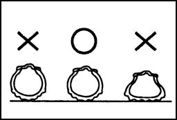 If it is loose, tighten it to specified torque.
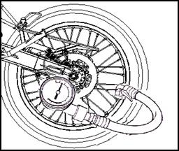
 Change a new tyre when decorative pattern depth on tyre middle reaches the degree of the right picture.
 Back shaft nut 100-113NЎ¤m
 1.3.1 Removal