Заглавная страница Избранные статьи Случайная статья Познавательные статьи Новые добавления Обратная связь КАТЕГОРИИ: ТОП 10 на сайте Приготовление дезинфицирующих растворов различной концентрацииТехника нижней прямой подачи мяча. Франко-прусская война (причины и последствия) Организация работы процедурного кабинета Смысловое и механическое запоминание, их место и роль в усвоении знаний Коммуникативные барьеры и пути их преодоления Обработка изделий медицинского назначения многократного применения Образцы текста публицистического стиля Четыре типа изменения баланса Задачи с ответами для Всероссийской олимпиады по праву 
Мы поможем в написании ваших работ! ЗНАЕТЕ ЛИ ВЫ?
Влияние общества на человека
Приготовление дезинфицирующих растворов различной концентрации Практические работы по географии для 6 класса Организация работы процедурного кабинета Изменения в неживой природе осенью Уборка процедурного кабинета Сольфеджио. Все правила по сольфеджио Балочные системы. Определение реакций опор и моментов защемления |
Нечёткий регулятор натяжения
Напряжение между клетями может быть измерено путём установки тензодатчиков или получено из других обнаруженных физических переменных [11]. Таким образом, регулирование натяжения можно разделить на прямые и косвенные схемы.
Из-за физических ограничений на большинстве прокатных станов межклетевое напряжение в предлагаемой системе косвенно определяется путём определения тока якоря двигателя. То есть метод сравнения косвенного тока [11] используется для достижения контроля напряжения. Разница
и токе якоря до и после попадания заготовки в следующую клеть ниже по потоку указывает на возникновение переднего межклетевого напряжения. Если ток устройства контролируется для отслеживания его значения до того, как заготовка попаёт в нижнюю трибуну, переднее напряжение будет доведено до нуля.
Нечёткий регулятор напряжения измеряет как разность так и изменение разности тока устройства до и после попадания заготовки в нижнюю клеть в качестве входных данных. Он имитирует человека-оператора и основан на нечётких рассуждениях типа Мамдани и Сугено для генерации корректирующего сигнала для скорости двигателя вышестоящей клети.
Возьмём е-клеть за текущую разницу между током без прямого натяжения и фактическим током устройства ι-й клети, ∆ ея изменение в текущей
разности и ∆ vя поправка на опорную скорость ASR ι-й клети. Выход регулятора для
каждой клети может быть выражен как
где
Выбираются пять треугольных функций принадлежности для текущей разницы (Ошибка), три функции принадлежности для изменения разности (Изменение ошибки) и семь симметричных нечетких одиночных элементов выбираются для коррекции выходной скорости (Выход). Эти функции принадлежности определяются следующим образом. Ошибка: NB [-1, -1, -0,6, -0,3], NS [-
0,6, -0,3, 0], Z [-0,3, 0, 0,3], PS [0, 0,3, 0,6], PB [0,3, 0,6,
1, 1]; Изменение ошибки: N [-1, -1, -0,5, 0], Z [-0,5, 0, 0,5],
P [0, 0,5, 1, 1]; Выход: NB [-0,75], NM [-0,5], NS [-
0,25], Z [0], PS [0,25], PM [0,5], PB [0,75]. База правил содержит пятнадцать правил, как показано в таблице 1. Масштабирование
факторы выбираются как kе, я = 0,4, k ∆ е, я = 1.5, и kv, я = 0,1.
Алгоритмы управления по формуле. (1) реализованы в цифровом виде в программах Modicon PLC.
Таблица 1 База правил
Виртуальный прокатный тест
Первоначальная установка стана, предписывающая эталонную скорость каждой клети прокатного стана, обычно предназначена для установления теоретически «идеального» условия согласования скоростей на основе принципа сохранения массы и параметров клети для каждого производственного графика. Такая установка стана необходима для запуска процесса, хотя в действительности она не может обеспечить идеального согласования скорости из-за сложной динамики деформации и других внешних помех.
Растяжение между стойками возникает из-за несоответствия скорости. Чтобы оценить на виртуальном прокатном стане систему нечёткого контроля натяжения с несколькими клетями, перед прокаткой создаётся рассогласование скорости для каждой межклетевой зоны. Это было сделано путём отклонения скорости двигателя предшествующей клети от выбранной начальной настройки стана. Выбранный производственный график имеет скорость окончательной обработки 800 футов в минуту. Начальный размер заготовки 5,5 дюйма2 и размер продукта 0,75 дюйма2. В таблице 2 показаны преднамеренно изменённая начальная скорость каждой черновой клети и напряжение в каждой межклетевой зоне после прокатки первой заготовки.
Таблица 2: Начальная и конечная скорость двигателя и межклетевое напряжение каждой межклетовой зоны в повторяющемся и интервальном режиме.
После 5 заготовок все межклетевые напряжения доводятся до очень незначительных значений. После 18 заготовок все межклетевые зоны приводятся в состояние без напряжений.
с таблице 2 также показаны конечные скорости черновых клетей и окончательные значения межклетевых напряжений (данные в скобках). Для оценки переходных характеристик системы управления на рис. 4 и 5 показаны общие характеристики тока устройства и скорости двигателя выбранных клетей 4 и 5. Кривые отклика приведены для 20 прокатных заготовок. Фиг. 6 - увеличенный вид частичных откликов клети 5 для последних 5 заготовок. Видно, что ток устройства каждой клети хорошо отслеживает своё эталонное значение после нескольких заготовок. Обратите внимание, что удары тока, когда заготовка ударяется о контролируемую клеть или покидает её, или ударяется о её нижнюю клеть, неизбежны в процессе прокатки и не обрабатываются системой управления.
Заданное значение тока клети представляет собой ток якоря той клети в состоянии без прямого натяжения. Он отбирается для каждой заготовки и может включать обратное натяжение. Следовательно, текущее значение тока не фиксируется до тех пор, пока все межклетевые зоны не станут свободными от напряжения, как показано на рис. 4 и 5.
Из откликов скорости можно увидеть, что эталонная скорость стенда регулируется автоматически, чтобы она соответствовала скорости последующей клети. Мгновенное снижение и увеличение фактической скорости, происходящие, когда полоса ударяется о контролируемую клеть или покидает её, неизбежны и не контролируются системой контроля натяжения. Предусмотрена компенсация опережающей скорости, позволяющая снизить падение скорости из-за удара стойки до приемлемой степени. Можно ясно увидеть процесс автоматической регулировки скорости из первой половины увеличенного частичного отклика скорости на рис. 6.
в Заключение
Безпетлевое регулирование межклетьевого напряжения на черновых прокатных станах остаётся труднопреодолимой проблемой. В данной статье предлагается успешная многопозиционная нечёткая система управления натяжением для чернового прокатного стана. Результаты испытаний на виртуальном прокатном стане показывают, что предложенная технология позволила реализовать удовлетворительное управление натяжением нескольких клетей в процессе черновой прокатки.
Подтверждение
Эта работа была поддержана Канадским советом по естественным наукам и инженерным исследованиям (NSERC) в рамках гранта на совместные исследования и разработки CRDPJ 234028-99 и гранта IC403 на совместные исследования в области материалов и производства Онтарио. Авторы хотели бы также поблагодарить Quad Engineering Inc. за помощь в предоставлении испытательного оборудования и за полезные комментарии.
Рекомендации
3. Р. Такахаши, «Современное состояние управления процессом горячей прокатки», Инженерная практика управления, 9 (2001), стр. 987-993, 2001.
4. Х. Катори, Р. Хираяма, Т. Уэяма и К. Фурута, «О возможности бесконтактной прокатки в процессе горячей прокатки», Proc. 1999 Международная конференция IEEE по приложениям управления, т. 1.С. 18-22, 1999.
5. Г. Ли, «Разъединенный интеллектуальный контроль натяжения», Технический отчет, ITC.3 ( внутренний),Университет Райерсона,январь2002г.
6. Т. Хескет, Я. Цзян, DJ Клементс, Д.Х. Батлер и
Р. ван дер Лаан, «Контроллер для чистовых станов горячей прокатки», IEEE Trans. Технология систем управления, т. 6,вып. 2.С. 208-219, 1998.
6. Х. Иманари, Ю. Моримацу и К. Секигучи, «H-бесконечное управление петлителем для станов горячей прокатки»
IEEE Trans. Ind. Appl., т. 33,стр. 790-796,май/июнь 1997 г.
8. Ю. Секи, К. Секигучи, Ю. Анбе, К. Фукусима, Ю. Цуджи и С. Уэно, «Оптимальное многопараметрическое управление петлителем для чистового стана горячей прокатки», IEEE Trans. Промышленное применение, т. 27,нет. 1.С. 124-
130, январь-февраль 1991 г.
9. М. Шиоя, Н. Ёситани и Т. Уэянма,
«Невзаимодействующее управление с возмущением компенсация и ее применение для управления натяжным устройством для стана горячей прокатки», Proc. 1995 IEEE
21-я Международная конференция по промышленности
Электроника, управление и приборы, IECON 1995, т. 1.С. 229-234, 1995.
и Ф. Джанаби-Шарифи и Дж. Фан, «Самонастраивающееся управление нечетким петлителем для прокатных станов», Proc. 39-я конференция IEEE по решениям и контролю, т. 1.
С. 376-381, 2000.
и Ф. Джанаби-Шарифи, "Нейро-нечеткое управление петлей с T-оператором и настройка правил для прокатных станов: теория и сравнительное исследование", Proc. 27-я Ежегодная конференция IEEE «Промышленная электроника», IECON 2001, Ноябрь2001г.,Denver, Co., стр. 58-63, 2001.
и Л. Виницкий и Р. Ли, «Виртуальный прокатный стан для настройки системы
управления в реальном времени, обучения операторов и моделирования прокатного стана», Ассоциация инженеров черной металлургии,
1999 г.
[11] И. Шпансер и В. Кинснер, "Исследование архитектуры системы контроля натяжения для прокатных станов Манитобы", Предложение по исследовательскому проекту 0037-002 ( внутренний), 1983.
Рис. 4 Общие характеристики тока и скорости стенда 4
Приложение № 2
Abstract Two alloys grades for work rolls used in the roughing stand of Hot Strip Mill (HSM) are compared. The first grade known as High Chromium Steel (HCS) is presently the most widely used alloy for such an application, while the second one known as semi-High Speed Steel (semi-HSS) is the new grade developed to improve the overall performance of the work roll in the roughing stands of the HSM.
In the present paper, the new semi-HSS grade is studied starting from three chemical compositions closed one to another, the variation in the alloying elements is intended to assess, on one hand the effect of a small increase of the carbon content, and on the other hand the influence of the addition ofa strong MC carbide forming element.
The comparison of HCS and semi-HSS grades involves many fields.
Regarding the metallurgical aspect, such a comparison led to the enhancement of the solidification range, the crystallization behavior and the microstructure in the as-cast condition for both grades.
Furthermore, corrosion behavior and performances of the work rolls in service are compared.
Various techniques are used in order to characterize both grades, such as Differential ThermalAnalysis (to determine phase transformations temperatures, the crystallization behavior and the interval of solidification), hardness measurements, optical microscopy, scanning electron microscopy associated with energy dispersive X ray spectroscopy (to determine the nature and the composition of phases, especially matrix and carbides).
Finally micro-macro relations between the nature of the microstructure and the properties of HCS and semi-HSS rolls grades in service conditions could be established.
Introduction In the early 80's, the Chromium steel work roll grade was developed by European rollmakers and introduced since then in most of the existing roughing stands of hot strip mills (HSMs) as well as into the early finishing stands of compact strip mills. In 2010, the Chromium steel grade is still a standard grades in many HSMs over the world as can be derived from figure 1.
The ever increasing requirements for roughing mills in terms of cost/performance ratio including higher throughput, improved product quality and higher safety have stimulated European rollmakers to develop in the early 90“s a new roll grade for roughing stands which is known as semi-High- Speed Steel (semi-HSS). This new grade was considered as a real revolution in terms of roll performance in nearly all aspects of required behaviour.
Figure 2: History of'hsm roughing mi// worA
2 Work rolls grades for Roughing stands 2.1 Chemical composition
The typical chemical compositions of the main roughing roll grades used nowadays in hot strip rolling are listed in table 1. This table indicates the main elements such as Carbon, Chromium, Tungsten equivalent, MC-carbide forming elements as well as the carbide content and hardness range of the different roughing roll grades.
Semi-HSS 1and semi-HSS 2 are respectively semi-HSS grade with different carbon content, both grades contain MC- carbides forming elements, the semi-HSS 3 shows the highest MC-carbide forming elements content(V, Ti, Nb, Ta, etc.).
Table 1: Roughing Mill Roll Grades — Analysis, carbide content and hardness of working zone
The Chromium steel grade (Cr-steel) microstructure is mainly determined by a matrix of tempered martensite with eutectic carbides of the M,C3 and M,C type. The highly increased hardness of matrix and of the different carbide types other than cementite have determined a much higher wear resistance and fire crack resistance compared to former standard grades. In the mid 80“s, this roll type became a standard roughing mill work roll grade. The semi-HSS grade is characterized by a matrix of tempered martensite with a strong effect of temper hardening, where special carbides of the M,C3, M,C and MC type are embedded. This structure already offers the typical characteristics of HSS grades like high temperature strength and hot hardness. The latest developed HSS grade for roughing stands, has increased amounts of MC and M,C carbides replacing to a higher extent the M,C3 type carbides. Both semi-HSS and HSS for roughers do not present a continuous carbide network. These last two roll grades are submitted to a long sophisticated heat treatment which is responsible for the homogeneous basic structure and contributes to their high performance level.
The type, hardness and amount of these carbides have a strong influence on wear resistance, surface deterioration and oxidation behaviour of the different roll types [1-5].
The present work will be focused on Cr-steel and the three semi-HSS work rolls.
2.2 Microstructures
Many different roll grades have been used in roughing stands of HSMs since the beginning of hot strip rolling [6]. Only some recent roll grades will be discussed in some more details. The microstructures of these grades are shown in figure 3. Figure 3: Overview of work rolls microstructures for roughing stands — 400x nital etching 3. Metallurgical characterization 3.1 Thermodynamical simulations
Thermodynamical simulations were obtained from Thermo- Calc0 software (TC). Example of equilibrium diagrams of Cr- Steel and semi-HSS 3 are given at figures 4a to 4d. TC simulations assume constant equilibrium conditions which mean a very low cooling rate where ideal diffusion is allowed for all the alloying elements either in the liquid or in the solid state. These figures show the phase volume fraction of stable phases in the studied alloys between 500 and 1500°C with a 10°C step. From TC simulations, it appears that the first solid is almost the face centered cubic austenite except for the semi-HSS 3 grade where the first solid to precipitate is the bold-centered cubic delta ferrite. From this statement a peritectic transformation occurs in the semi-HSS 3 grade during the solidification process (fig. 4d). This peritectic transformation is known to promote a new austenite phase from the decomposition of the previous delta ferrite phase.
Figure 4.a: Phase yo/ume” ’racfion evolution on cr-sfee/ -
Figure 4.b: Phase v'o/time fracf/ons on semi-fuss 1 - equilibrium conditions
Figure 4.c: Phase volume fractions on semi-hss 2
Figure 4.d: Phase v'o/ume fraction eyo/ut/on on
As M,C, carbides in both Cr-Steel and semi-HSS grades 1 and 2 seem to start their precipitation closed to or below the solidus temperature, with an increase of their amount with decreasing temperature, these carbides could be assume to be of eutectoid type. Only MC carbides found in semi-HSS 3 through the equilibrium diagram could be considered like real eutectic as they precipitated from the liquid. Thus in equilibrium conditions, semi-HSS grades 1 and 2 didn't exhibited eutectic carbides, as M,C, and latter M,C precipitated in the solid state.
Furthermore, in equilibrium conditions all the primary carbides (MC, M,C3 and M,C) transform themselves closed to the A1 point (see fig. 4a to 4d), in a partial or complete reaction that leads to other types of carbides known as fine secondary carbides, such as M„C„ M,C and MC, when the temperature decreases.
Solidification paths Solidification paths were obtained from Differential Thermal Analysis tests. From this technique, a difference in energy is measured between the material to be tested and an inert reference material as a function of temperature while both samples are submitted to a controlled temperature program. A phase transformation occurring in the studied material appears as an endothermic or an exothermic peak when the DTA cycle goes on [7].
Figure 5 illustrates the results of DTA tests on the four grades during the cooling cycle which starts from the melt down to room temperature at5°C/min. Figure 5: Solidification sequences on the four studied a//oys during dta cooling stage at 5°c/min The solidification range was obtained while considering the liquidus and the solidus temperatures on the four studied grades. Table 3 gives the results obtained from the comparison between equilibrium (from TC) and non-equilibrium (from DTA) conditions.
Figure 6.a: Eutectic carbides network on cr-stee/ affer dta test — fis/ibone-like m,c, (grey) and fine-lamellar m,c (light) nital etching b: Complex m,c/m,c eUfecfic carbide in a
cr-steel and related eds mapping showing major e/ements of each phase (cr-rich m,c, and mo-rich m,c) nital etching Only the starting points of M,C3 and M,C which are considered as eutectoid carbides in the equilibrium conditions are illustrated in table 3. It was observed that phase transformation range is shorter in the non-equilibrium conditions than that of the equilibrium conditions.
From the comparison between Cr-Steel and semi-HSS grades, the following observations arise:
The liquidus temperature of semi-HSS grades is always higher than the Cr-Steel one whatever the conditions are from equilibrium or non- equilibrium;
The semi-HSS 3 exhibits the higher liquidus temperature in the non-equilibrium conditions (1428°C);
The semi-HSS 3 grade contains MC eutectic carbides which precipitate at high temperature (1353°C); as a consequence, no M,C, are found in this alloy and M,C precipitated earlier (1158°C) when compared to the related eutectic transformations on Cr-Steel, semi-HSS 1 and semi-HSS 2 grades;
Eutectic M,C, and M,C carbides have got their precipitation temperature higher and more distinguishable in Cr-Steel than the equivalent ones in semi-HSS grades 1 and 2 in the DTA solidification sequence;
From the comparison between equilibrium and non equilibrium conditions, the following observations are made:
Liquidus temperature obtained by DTA is always above the one obtained from TC simulation; The first solid to precipitate in the non equilibrium conditions is not correctly found by TC simulation, as it was the case for the three semi-HSS grades where delta-ferrite precipitate first instead of austenite; Eutectic carbides found in non equilibrium conditions appear only in solid-state transformations in the equilibrium conditions and so they must be considered like eutectoid carbides; The solidification range is always larger in the non equilibrium conditions than that found in TC simulation, even if the first solid to form is the same in both conditions (see the case of Chromium steel);
Eutectic carbides obtained from continuous cooling of the melt are still present at room temperature, unlike the corresponding ones found in the equilibrium conditions, as the latter disappear with solid-state transformation; in fact M,C, and M,C transform themselves respectively in M„C, and M,C in the TC simulation.
The differences observed between non equilibrium and equilibrium simulations could be explained on several ways.
Delta ferrite that appears in the semi-HSS grades during non equilibrium DTA tests could probably arise from inclusions (sulphides or oxides) as they are known to be delta-ferrite germs and they can promote non heterogeneous nucleation [9].
While equilibrium conditions assume a full diffusion of all the alloying elements, there is a segregation phenomenon in the non equilibrium conditions, especially within the interdendritic space where strong carbides forming elements such as Nb, Mo, Cr that are gamma-incompatible, are rejected when the growing dendrite is of the austenite type.
| ||||||||||||||||||||||||||||||||||||||||||||||||||||||||||||||||||||||||||||||||||||||||||||||||||||||||||||||||||||||||||||||||||||||||||||||||||||||||||||||||||||||||||||||||||||||||||||||||||||||||||||||||||||||||||||||||||||||||||||||||||||||||||||||||||||||||||||||||||||||||||||||||||||||||||||||||||||||||||||||||||||||||||||||||||||||||||||||||||||||||||||||||||||||||||||||||||||||||||||||||||||||||||||||||||||||||||||||||||||||||||||||||||||||||||||||||||||||||||||||||||||||||||||||||||||||||||||||||||||||||||||||||||||||||||||||||||||||||||||||||||||||||||||||||||||||||||||||||||||||||||||||||||||||||||||||||||||||||||||||||||||||||||||||||||||||||||||||||||||||||||||||||||||||||||||||||||||||||||||||||||||||||||||||||||||||||||||||||||||||||||||||||||||||||||||||||||||||||||||||||||||||||||||||||||||||||||||||||||||||||||||||||||||||||||||||||||||||||||||||||||||||||||||||||||||||||||||||||||||||||||||||||||||||||||||||||||||||||||||||||||||||||||||||||||||||||||||||||||||||
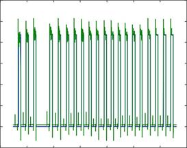
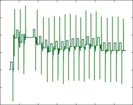


 Figure 1: Dominant roughing mill work roll grades in ffie world

 Semi-HSS acquired a strong position especially in Western European HSMs. However, some applications like stainless and special steel rolling have shown interest of further development to overcome some insufficiencies of semi-HSS. A special High-Speed Steel (HSS) grade for roughing mill application was developed to meet this new challenge in the late nineties — see history of work roll development in figure 2.
 roll grades 1950-2010

 equilibrium conditions

 - equilibrium conditions
 semi-hss 3 - equilibrium conditions
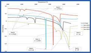
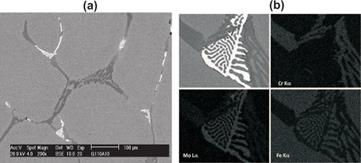 SEM-EDS analyses (Figures 6a and 6b) performed after DTA tests allow the identification of the phases present at room temperature, like all the eutectics carbides and the matrix (mixture of martensite and retained austenite). Such a DTA solidification sequence had already been enhanced in previous work[8-10].

 37
37

3.4 Hardness features
Hot hardness had been determined on three of the four studied grades with regard to HSS for roughers as a reference.
 Figure 8 gives the hot hardness behaviour of 3 studied grades and HSS rougher in addition.

 Both semi-HSS grades 2 and 3 seem to have similar and flat hot hardness behaviours except for temperature above 570°C where hot hardness of semi-HSS grade 3 decreases slowly when that of semi-HSS grade 2 collapse. Such a levelling of the hot hardness above 570°C on semi- HSS 3, which is also observed on HSS for roughers, is probably due to the presence of a higher amount of MC carbides on both compared to semi-HSS grade 2 or Cr-Steel.
 “End of the eutectic reaction from DTA tests
3.3  Microstructures through SEM analysis
Typical microstructures of studied rolls are given in figure 7a to figure 7d as obtained from scanning electron microscope (SEM). The microstructure of all rougher grades in the service conditions consists of a non continuous network of eutectic carbides located at grain boundaries, with a tempered martensitic matrix. Such a distribution of carbides is common for HSS grades [8, 10].

200 300
600 700
Temperature (°C)

 Figure 8: Hot harcfness (shore c) on semi-hss grades 2 and 3,
cr-stee/, and /iss for roughers (as reference)
3.5 Corrosion behaviour
Figure 7.a: CR- steel (near ffie surface of the shell) nefwork
of eufecfic m,c,(fishbone-like, grey) and m,c (light) carbides at grain boundaries, in an untempered Martensitic matrix. Nital etching.
Figure 7.b: Serni-hss 1(cIose to the scrap diameter) network of er/fecfic m,c, (grey) and m,c (Iight)carbides at grain boundaries, in a tempered Martensitic matrix. ñ/ifa/ etching.
 |
Figure 7.c: Semi-hss 2 (close to the scrap diameter) - network of eutectic mdc, (bulh, grey) and m,c (light) at grain boundaries, in a tempered Martensitic matrix. Nital etc/iing.
Figure 7.d: Semi-hss 3 (near the surface of fhe she//j — netw'ork of eclectic mc (chinese script, light) and m,c (rod-like, light) carbides at grain boundaries, in an untempered Martensitic matrix. Nital etching.
Some static corrosion tests were performed in a liquid medium on Cr-steel and semi-HSS 3 in laboratory with the following conditions: 60°C — holding time from 4 to 27 h —[CIX from 350 to 1000 ppm and [HOCI-] from 0 to 5 ppm. Figure 9 shows the results obtained on the surface of the samples at the end of the corrosion tests. Semi-HSS 3 appears to exhibit a less corroded surface than Cr-Steel, as pits found on the previous are smaller than those found on the latter.
4. Roll behaviour in service