Заглавная страница Избранные статьи Случайная статья Познавательные статьи Новые добавления Обратная связь КАТЕГОРИИ: ТОП 10 на сайте Приготовление дезинфицирующих растворов различной концентрацииТехника нижней прямой подачи мяча. Франко-прусская война (причины и последствия) Организация работы процедурного кабинета Смысловое и механическое запоминание, их место и роль в усвоении знаний Коммуникативные барьеры и пути их преодоления Обработка изделий медицинского назначения многократного применения Образцы текста публицистического стиля Четыре типа изменения баланса Задачи с ответами для Всероссийской олимпиады по праву 
Мы поможем в написании ваших работ! ЗНАЕТЕ ЛИ ВЫ?
Влияние общества на человека
Приготовление дезинфицирующих растворов различной концентрации Практические работы по географии для 6 класса Организация работы процедурного кабинета Изменения в неживой природе осенью Уборка процедурного кабинета Сольфеджио. Все правила по сольфеджио Балочные системы. Определение реакций опор и моментов защемления |
Audio Control Panel Controls⇐ ПредыдущаяСтр 14 из 14
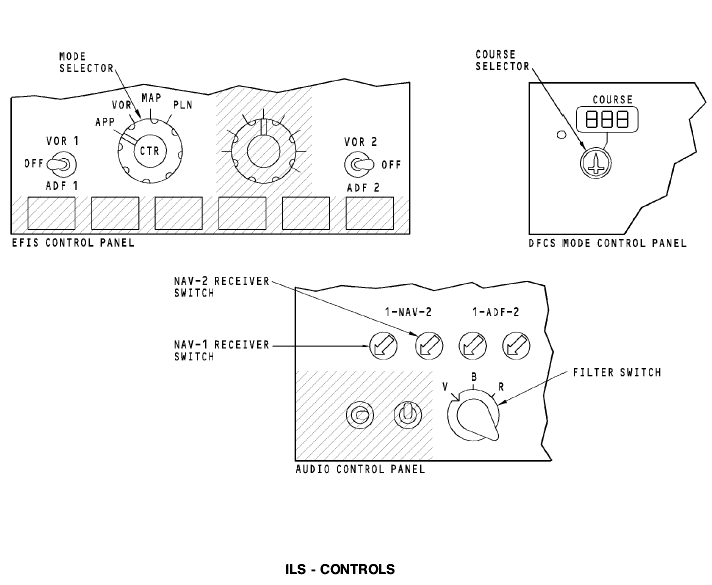
The audio control panels (ACPs) lets the crew listen to ILS station audio or the morse code station identifier. You use the ACP receiver switches to select the ILS audio you want to listen to. The NAV 1 receiver switch selects the MMR 1 audio and the NAV 2 receiver switch selects the MMR 2 audio. The filter switch lets you listen to only voice audio in the voice (V) position. The range ® position lets you listen to the station morse code identifier. With selector in the both (B) position you can listen to both the voice audio and the morse code station identifier.
ILS - STANDBY ATTITUDE INDICATOR DISPLAYS General The standby attitude indicator gives the crew an alternate attitude indication source. The indicator also provides ILS data. You use the approach selector on the indicator to show ILS data. The approach selector has these positions: · Off - no ILS data on indicator · APP - ILS localizer and glideslope data shows · B/CRS - back course ILS localizer data shows.
Indications When the selector is in the OFF position, the localizer and glideslope deviation bars do not show. When the selector is in the APP position, the localizer and glideslope deviation bars show. When you select B/CRS, the localizer deviation bar reverses polarity for the approach display and the glideslope deviation bar goes out of view. When the indicator receives invalid ILS data, the localizer or glideslope deviation bars go out of view and the glideslope flag or localizer flag shows. When the ILS data is no computed data (NCD) for localizer or glideslope data, the related deviation bar goes out of view.
General To show ILS displays on the ADI you must tune a valid ILS frequency on the NAV control panel and select it to the active display window. Normal Display The localizer deviation pointer and scale show at the bottom of the attitude display. The scale is a standard four dot scale. One dot equals 1 degree of deviation. The deviation indication shows deviation to the left or right of the runway centerline. The localizer scale shows in white and the localizer pointer shows in magenta. The localizer scale can show the standard display or the expanded scale. A two-dot expanded scale can replace the four-dot scale. For the expanded scale, each dot equals 0.5 degrees of deviation. The white expanded scale goes to amber and flashes when the autopilot sends an ILS deviation warning. The expanded scale shows for these conditions: · LOC deviation is less than 5/8 dot · LOC or APP mode is engaged · ILS course and the airplane track are within 5 degrees of each other · An autopilot is in CMD.
The glideslope deviation pointer and scale show to the right of the attitude display. The scale is a standard four-dot scale. One dot equals 0.35 degrees of deviation. The pointer gives fly-to commands to intercept the glideslope beam. The glideslope scale shows in white and the glideslope pointer shows in magenta. There is no expanded scale for glideslope deviation. The ILS station frequency and course show above and to the right of the ADI. If the ILS ground station transmits a morse coded station identifier, the stations letter identifier replaces the numeric frequency display when the receiver captures the signal. Rising Runway
The rising runway shows when there is a LOC signal capture and the radio altitude is below 2500 feet. The symbol goes out of view above 2500 feet. The rising runway symbol is green with a magenta stem. The rising runway symbol represents the radio altitude above the runway. It moves laterally with the localizer deviation pointer to show localizer deviation. The symbol starts to move when the radio altitude is 200 feet. It touches the airplane symbol when the radio altitude is 0 or at touchdown. NCD Display
When the ILS data goes to an NCD condition, the CDS shows the localizer and glideslope scales and removes the pointers.
Fail Display
The amber LOC flag replaces the localizer deviation pointer and scale when the localizer receiver function has a failure. The amber G/S flag replaces the glideslope deviation pointer and scale when the glideslope receiver function has a failure.
ILS - EXPANDED ILS DISPLAY General To show ILS displays on the CDS, set the EFIS control panel mode selector to the APP position. You must also tune a valid ILS frequency on the NAV control panel. Normal Display The glideslope deviation pointer and scale show at the right of the NAV display. The glideslope deviation pointer is magenta and the scale is white. The glideslope scale is the standard four dot scale where each dot equals 0.35 degrees of deviation. The glideslope deviation pointer gives fly-to signals to intercept the glideslope beam. The course pointer points to the number that you set on the DFCS MCP. For ILS, you use the DFCS MCP course selector to enter the ILS course (airport runway heading). The localizer deviation indicator and scale shows at the bottom of the NAV display. The localizer scale is white and the localizer deviation indicator is magenta. The deviation scale is the standard four dot scale. One dot is equal to 1 degree of deviation. The localizer deviation indicator shows the deviation to the left or right of the runway centerline. The NAV data source shows in white at the upper right corner of the display. It shows the source of the data for the ILS displays. To the right of the NAV data source is the active ILS frequency display. The ILS frequency display shows the active ILS frequency and the selected course. If the ILS ground station transmits a morse coded station identifier, the letter identifier replaces the numeric frequency when the receiver captures the ground station signal. NCD Display When the ILS data goes to an NCD condition, the CDS shows the localizer and glideslope scales and removes the pointers. Fail Display For invalid ILS data, the CDS replaces the localizer deviation scale and indicator with the amber LOC flag when the localizer receiver fails. The amber G/S flag replaces the glideslope deviation scale and pointer when the glideslope receiver fails. ILS - CENTERED ILS DISPLAY General To show the centered ILS NAV display, push the CTR switch on the EFIS control panel mode selector switch. Normal Displays The glideslope deviation pointer and scale show to the right of the HSI display. The glideslope pointer is magenta and the scale is white. The glideslope scale is the standard four dot scale. Each dot equals 0.35 degrees of deviation. The pointer gives fly-to commands to intercept the glideslope beam. The course pointer points to the number that you set on the DFCS MCP. For ILS, you use the DFCS MCP course selector to enter the ILS course (airport runway heading). The localizer deviation indicator and scale show in the center of the HSI compass card. The localizer deviation indicator is magenta and the scale is white. The localizer scale is the standard four dot scale. Each dot is equal to 1 degree of deviation. The deviation indicator shows the deviation to the left or the right of the runway centerline. The NAV data source shows in white in the upper right corner of the display. It shows the source of data for the ILS display. The active ILS frequency shows to the right of the NAV data source. The ILS frequency display shows the active ILS frequency and the selected course. If the ILS ground station transmits a morse coded station identifier, then the letter identifier replaces the numeric frequency when the receiver captures the ground station signal.
NCD Display For an ILS NCD condition, the CDS displays the localizer and glideslope scales and removes the deviation bar and glideslope pointer. Fail Display For invalid ILS data, the CDS replaces the localizer scale and deviation indicator with the amber LOC flag when the localizer receiver fails. The amber G/S flag replaces the glideslope scale and pointer when the glideslope receiver fails.
Test When you push the test switch, the MMR does a check of the internal operation and its interface with other airplane systems. The test takes approximately 36 seconds. This is the test sequence that shows on the LED status indicators during the test: · 0 to 2 seconds - the LRU STATUS, the CONTROL FAIL, and the ANT FAIL LEDs come on red · 2 to 4 seconds - the LRU STATUS LED is green and theCONTROL FAIL LED is red · 4 to 6 seconds - all LEDs go off · 6 to 36 seconds - test status shows.
The LRU STATUS segment shows red when there is an internal failure in the MMR. Green shows that the MMR is operating normally. The CONTROL FAIL segment shows red when an interface to the MMR has a failure. Green shows that all the interfaces to the MMR are normal. NOTE: The ANT FAIL LED is not used at this time.
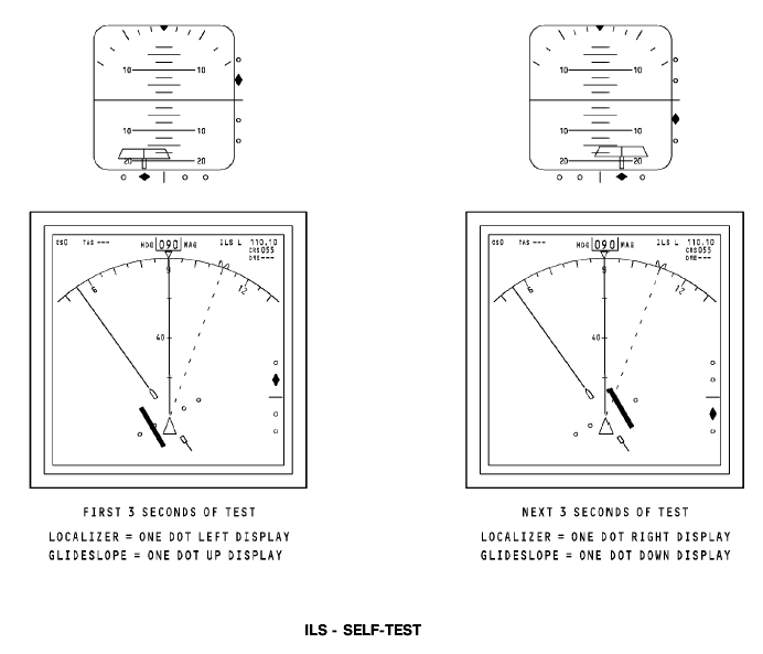
ILS - SELF-TEST Test You use the NAV control panels to do an ILS test from the flight compartment. The captain NAV control panel does a test of MMR 1 and the first officer NAV control panel does a test of MMR 2. You need to set these controls to do an ILS test: · Enter a valid ILS frequency into the active frequency display window on the NAV control panel · Set a course on the DFCS mode control panel that is within 90 degrees of the airplane heading · Push the test switch on the NAV control panel. To see the ILS test on the NAV display, you must select the approach (APP) mode on the EFIS control panel mode selector. This is the display sequence that shows on the CDS during the ILS test: · For the first 3 seconds, one dot left of localizer deviation and one dot up of glideslope deviation · For the next 3 seconds, one dot right of localizer deviation and one dot down of glideslope deviation · Displays return to normal indications.
Marker Beacon System В737. Подробно рассматривается в [4] рекомендуемой литературы. General The marker beacon system supplies visual and aural indications when the airplane flies over airport runway marker beacon transmitters. Abbreviations and Acronyms · A/P - autopilot · AC - alternating current · ACP - audio control panel · ALT - alternate · AMP - amplifier · B - both · BITE - built-in test equipment · CDS - common display system · DEU - display electronics unit · DME - distance measuring equipment · FDAU - flight data acquisition unit · DU - display unit · FT - functional test · GND - ground · Hz - hertz · I/C - intercom · ILS - instrument landing system · IM - inner marker · I/O - input/output · LCD - liquid crystal display · LED - light emitting diode · LRU - line replaceable unit · MAINT - maintenance · MB - marker beacon · MHz - mega hertz · MM - middle marker · NAV - navigation · NC - not connected · ND - navigation display · NORM - normal · NVM - non-volatile memory · OM - outer marker · PFD - primary flight display · R - range · REU - remote electronics unit · RF - radio frequency · R/T - receive/transmit · RCVR - receiver · STA - station · TFR - transfer · V - voice · V - volt · VHF - very high frequency · VOR - vhf omnidirectional ranging
GENERAL DESCRIPTION General The marker beacon system has an antenna and a VOR/marker beacon (VOR/MB) receiver. The marker beacon function only operates in the VOR/MB receiver 1 position. Operation The marker beacon antenna receives the marker beacon signals. The signals go to the VOR/MB receiver 1. The VOR/MB receiver 1 supplies this data: · Marker beacon audio to the remote electronics unit (REU) · Marker beacon data to the common display system (CDS) display electronics unit (DEU) · Marker beacon data to the flight data acquisition unit (FDAU). The displays show marker beacon data.
COMPONENT LOCATIONS General The marker beacon antenna is on the bottom of the fuselage. The VOR/MB receiver 1 is in the electronic equipment compartment E1-2. The marker beacon data shows on these display units: · Left outboard display unit · right outboard display unit.
INTERFACES Power The VOR/marker beacon (VOR/MB) receiver 1 uses 115v ac power from the standby bus. Antenna Interface The marker beacon antenna sends radio frequency (RF) signals to the VOR/MB receiver 1. PSEU The proximity switch electronics unit (PSEU) supplies an air/ ground discrete signal to the VOR/MB receiver 1. The VOR/MB receiver uses this signal for these functions: · Prevent a test in the air · Count flight legs. Audio Interface
The VOR/MB receiver 1 sends marker beacon audio to the remote electronics unit (REU). The REU supplies marker beacon audio to the flight compartment. Marker Beacon Data The VOR/MB receiver 1 supplies marker beacon data to the 1 and 2 common display system (CDS) display electronics units (DEU). The receiver also supplies marker beacon data to the FDAU.
VOR/MARKER BEACON RECEIVER General The VOR/marker beacon (VOR/MB) receiver has these two parts: · VOR receiver · Marker beacon receiver. The marker beacon system operates in the VOR/MB receiver 1 position. The marker beacon receiver receives 75 MHz signals. Test and Indications You do a test of the these VOR/MB receiver 1 functions at the same time: · VOR function · MB function.
There is a test switch and two light emitting diodes (LEDs) on the front panel of the VOR/MB receiver. Flight Fault Memory The VOR/MB receiver has a nonvolatile flight fault memory. Only shop personnel can read the memory.
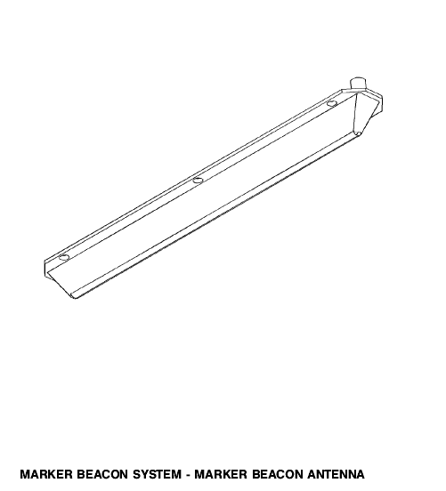
MARKER BEACON ANTENNA General The marker beacon antenna receives signals from marker beacon ground stations. Six screws hold the antenna to the fuselage.
DISPLAYS AND AUDIO OUTPUTS General When the airplane goes above a marker beacon transmitter, marker beacon data shows on the primary flight display (PFD). If you want to hear marker beacon audio, you select the marker beacon audio on the audio control panel (ACP). Display Types OM shows when the airplane goes above the outer marker. The OM letters are cyan. MM shows when the airplane goes above the middle marker. The MM letters are yellow. IM shows when the airplane goes above the inner marker, backcourse marker, or an airways marker. The letters IM are white. NCD/Fail Display If marker beacon data fails or is no computed data (NCD), the display does not show. Audio General The ACP supplies control signals to the remote electronics unit (REU). The REU uses the control signals to select the audio that goes to the flight interphone speakers and headsets. Use the ACP to listen to marker beacon audio. Audio Operation You make these ACP selections to listen to marker beacon audio: · Push the marker beacon receiver volume control to make the marker beacon audio come on · Turn the marker beacon receiver volume control to change the volume level. Audio Outputs These are the marker beacon audio outputs: · Outer marker (OM) is 400 Hz, continuous dashes (- - - -) · Middle marker (MM) is 1300 Hz, alternate dots and dashes (-.-.-.-.-) · Inner marker (IM) is 3000 Hz, continuous dots (......) · Backcourse marker is 3000 Hz, continuous paired dots (........) · Airways marker is 3000 Hz with the morse code. identifier for that station.
FUNCTIONAL DESCRIPTION Marker Beacon Signal The marker beacon antenna receives the 75 MHz signal and sends it to a 75 MHz filter in the VOR/marker beacon (VOR/MB) receiver 1. This filter tunes and rejects unwanted signals. The output goes to a radio frequency (RF) amplifier. A detector receives the amplifier output and sends the demodulated signal to three bandpass filters. The bandpass filters are at 400 Hz, 1300 Hz, and 3000 Hz. The filters send the signals to an audio amplifier and to an input/ output (I/O) card. The audio amplifier sends audio tones to the REU. The I/O card sends data to the DEU and the flight data acquisition unit (FDAU). The DEU shows marker beacon data on the PFDs. Monitor and Test The test switch starts a test of the VOR/MB receiver. The built-in test equipment (BITE) circuits do a test of the VOR/MB receiver. The test results show on the common display, light emitting diodes (LEDs), and through the flight interphone speakers and headsets. During the test, a self-test frequency generator gives a 75 MHz RF signal that has 400 Hz, 1300 Hz, and 3000 Hz audio signals. The bandpass filters find the audio signals and send them to the audio amplifier. The audio amplifier sends the audio signals to the REU. The REU sends the audio signals to the flight interphone speakers and headsets in the flight deck. The BITE circuits monitor the condition of the output data of the VOR/MB receiver. The VOR/MB receiver gets an air/ground discrete signal from the proximity switch electronics unit (PSEU). The VOR/MB receiver uses this signal to prevent a test in the air. An internal nonvolatile fault memory (NVM) in the BITE circuits use the air/ground discrete signal. The NVM uses this signal to calculate flight legs.
TEST – 1 General When you do a test of the marker beacon system, you test the VOR receiver 1 at the same time. Operation When you push the test switch, the receiver does a check of the internal receiver operation and the interface with the NAV control panel. The test takes 48 seconds. This is the test sequence that shows on the LED status indicators during the test: · 0 to 2 seconds - the LRU status and the control fail LEDs are red · 2 to 4 seconds - the LRU status LED is green and the control fail LED is red · 4 to 12 seconds - the LRU status and the control fail LEDs go off · 12 to 42 seconds - test status shows. The LRU status LED indicator shows green for an LRU test pass condition or red for an LRU test fail condition. The control fail LED shows red if there is no tune input from the NAV control panel or if the signal is invalid.
General You do a remote test of the navigation receivers with the navigation control panel. The navigation control panel does a test of these receivers: · VOR/MB receiver · ILS receiver. When you do a test of the marker beacon system, you do a test of the VOR/MB receiver 1 at the same time. Operation To do a test of the VOR/MB receiver 1, select a VOR frequency and push the test switch on the front panel of the navigation control panel. FT shows for common display system indications. You must select marker beacon audio on at least one of the ACPs to hear the audio tones. All the marker beacon audio tones come on in the flight compartment when you do the test. The audio tones come on continuously and you hear the outer, middle, and inner at the same time.
Вопросы для самоконтроля. 1. В чем состоят особенности радиосистем ближней навигации и радиосистем посадки? 2. Опишите принцип действия канала дальность РСБН. 3. Раскройте принцип действия канала азимута, реализующего импульсный метод. От чего зависит точность импульсного канала азимута? 4. Зарисуйте и разъясните структурную схему измерителя азимута РСБН. 5. Раскройте принцип действия канала азимута с фазовым методом измерения. Чем определяется его точность? 6. Раскройте принцип действия фазового канала азимута с доплеровским АРМ. 7. Опишите принцип действия и точность равносигнальных радиосистем посадки. 8. Опишите принцип действия радиосистем посадки с опорным нулем. 9. Опишите принцип действия двухканальных систем посадки. 10. Опишите принцип действия маркерного канала. 11. Назначение навигационно-посадочной аппаратуры. 12. Состав Курс МП -70. 13. Основные характеристики Курс МП -70. 14. Принцип действия навигационно-посадочной аппаратуры. 15. Органы управления и регулировки Курс МП -70. 16. Включение, проверка функционирования Курс МП -70. 17. Индикация и сигнализация. 18. В каком диапазоне частот работает КРП. 19. В каком диапазоне частот работает ГРП. 20. В каком диапазоне частот находятся каналы посадки. 21. В каком диапазоне частот находятся каналы навигации. 22. Кодовые сигналы маркерных маяков. 23. Что сигнализирует детектор «НА-ОТ». 24. Назначение переключателя «Маршрут-Посадка» на селекторе режимов. 25. В каком направлении совпадают фазы сигналов "Постоянная фаза" и "Переменная фаза" маяков VOR. 26. Выходные сигналы УНП Курс МП -70. 27. Выходные сигналы КРП Курс МП -70. 28. Выходные сигналы ГРП Курс МП -70. 29. Назначение переключателя МАРШРУТ – ПОСАДКА. 30. Назначение, состав, основные характеристики VOR В737. 31. Принцип работы VOR В737. 32. Интерфейс VOR В737. 33. Включение, проверка функционирования VOR В737. 34. Назначение, состав, основные характеристики ILS В737.
35. Принцип работы ILS В737. 36. Интерфейс ILS В737. 37. Включение, проверка функционирования ILS В737. 38. Назнач., состав, основные характеристики Marker Beacon System В737. 39. Принцип работы Marker Beacon System В737. 40. Интерфейс Marker Beacon System В737. 41. Включение, проверка функционирования Marker Beacon System В737.
Рекомендуемая литература. Основная 1. Сосновский А.А., Хаймович И.А. Радиоэлектронное оборудование летательных аппаратов. Справочник – М.: Транспорт, 1987г. 2. Учебное пособие. Радиоэлектронное оборудование ЛА. Составитель Кукушин В.А. Академия ГА, 2007г. 3. Учебное пособие. COMMUNICATION СВЯЗНОЕ ОБОРУДОВАНИЕ BOEING 737-600/700/800/900. Training Manual. Составитель Кукушин В.А. Академия ГА, 2008г. 4. Учебное пособие. NAVIGATION. Part 1. НАВИГАЦИОННОЕ ОБОРУДОВАНИЕ. Часть 1. BOEING 737-600/700/800/900. Training Manual. Составитель Кукушин В.А. Академия ГА, 2008г. 5. Учебное пособие. COMMUNICATIONS СВЯЗНОЕ ОБОРУДОВАНИЕ А-320. Training Manual. Составитель Кукушин В.А. Дополнительная 1. Aircraft Aerodynamic, Structures and Systems. Module 13: M13.04 Communication Navigation (ATA 23/34); M13.06 Equipment and Furnishings (ATA 25) / EASA Part-66 Training Handbook. – LINK&LEARN Aviation Training GmbH, 2007. – 176 p. 2. Эксплуатационная документация на аппаратуру. (Технические описания. Инструкции по эксплуатации. АММ).
|
|||||||||
|
|
Последнее изменение этой страницы: 2019-11-02; просмотров: 199; Нарушение авторского права страницы; Мы поможем в написании вашей работы! infopedia.su Все материалы представленные на сайте исключительно с целью ознакомления читателями и не преследуют коммерческих целей или нарушение авторских прав. Обратная связь - 18.226.169.94 (0.194 с.) |


 TEST – 2