Заглавная страница Избранные статьи Случайная статья Познавательные статьи Новые добавления Обратная связь КАТЕГОРИИ: ТОП 10 на сайте Приготовление дезинфицирующих растворов различной концентрацииТехника нижней прямой подачи мяча. Франко-прусская война (причины и последствия) Организация работы процедурного кабинета Смысловое и механическое запоминание, их место и роль в усвоении знаний Коммуникативные барьеры и пути их преодоления Обработка изделий медицинского назначения многократного применения Образцы текста публицистического стиля Четыре типа изменения баланса Задачи с ответами для Всероссийской олимпиады по праву 
Мы поможем в написании ваших работ! ЗНАЕТЕ ЛИ ВЫ?
Влияние общества на человека
Приготовление дезинфицирующих растворов различной концентрации Практические работы по географии для 6 класса Организация работы процедурного кабинета Изменения в неживой природе осенью Уборка процедурного кабинета Сольфеджио. Все правила по сольфеджио Балочные системы. Определение реакций опор и моментов защемления |
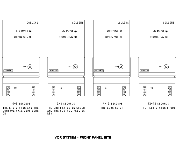
VOR system - front panel BITE
Test Push the test switch on the front panel to start a test of the VOR receiver. The test results show on the LED status indicators. There are two status LEDs. The LRU status LED can be red or green. The control fail LED is only red. When you push the test switch, the receiver does a check of the internal receiver operation and its interface with the NAV control panel. The test takes 48 seconds. This is the test sequence that shows on the LED status indicators during the test: · 0 to 2 seconds - the LRU status and the control fail LEDs are red · 2 to 4 seconds - the LRU status LED is green and the control fail LED is red · 4 to 12 seconds - the LRU status and the control fail LEDs go off · 12 to 42 seconds - test status shows. The LRU status LED indicator shows green for an LRU test pass condition or red for an LRU test fail condition. The control fail LED shows red if there is no tuning input from the NAV control panel or if the signal is invalid.
You can do a test of the VOR/MB receivers from the flight compartment with the NAV control panels. The captain’s NAV control panel does a test of VOR/MB receiver 1 and the first officer’s NAV control panel does a test of VOR/MB receiver 2. You need to set these controls to do a test of the VOR/MB receivers: · Enter a valid VOR frequency into the active frequency display window on the NAV control panel · Set a selected course of 000 on the DFCS mode control panel · Set the mode selector on the EFIS control panel to the VOR position · Push the test switch on the NAV control panel. This is the flight compartment display sequence that shows during the VOR test: · Invalid display (VOR flag) · NCD display (deviation bar out of view) · Test display (deviation bar centered).
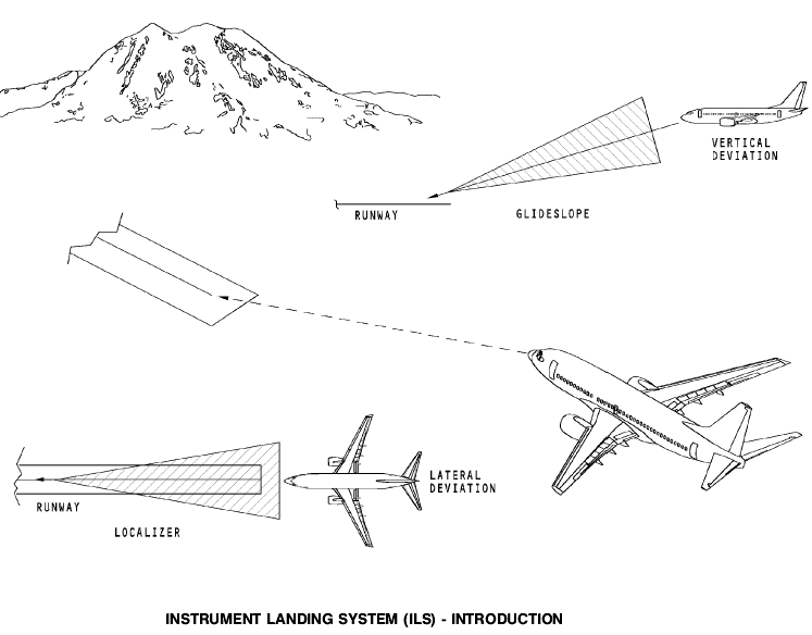
Instrument Landing System (ILS) В 737. Подробно рассматривается в [4] рекомендуемой литературы. Purpose The multi-mode receiver (MMR) contains the instrument landing system and the global positioning system functions. This section only covers the instrument landing system function. The instrument landing system (ILS) provides lateral and vertical position data neccessary to put the airplane on the runway for approach. The system uses signals from a glideslope ground station and a localizer ground station. The glideslope ground station transmits signals to give the airplane a descent path to the touchdown point on the runway. The localizer ground station transmits signals to give the airplane lateral guidance to the runway centerline.
Abbreviations and Acronyms · AC - alternating current · ACP - audio control panel · alt - alternate · altn - alternate · app - approach · ARINC - Aeronautical Radio, Inc. · BITE - built-in test equipment · BL - buttock line · CAPT - captain · DC - direct current · DEU - display electronics unit · DME - distance measurement equipment · EFIS - electronic flight instrument system · F/O - first officer · FCC - flight control computer · FDAU - flight data acquisition unit · FMC - flight management computer · freq - frequency · fwd - forward · grd - ground · ILS - instrument landing system · LCD - liquid crystal display · LED - light emitting diode · LRU - line replaceable unit · maint - maintenance · MHz - megahertz · MMR - multi-mode receiver · MKR - marker beacon · NAV - navigation · NCD - no computed data · ND - navigation display · norm - normal · PFD - primary flight display
General The instrument landing system (ILS) has two multi-mode receivers (MMRs) that contain the ILS function. The ILS function in the MMRs receive inputs from these antennas:
· VOR/LOC antenna · Localizer antenna · Glideslope antenna.
Description The receivers get manual tune inputs from the navigation (NAV) control panels.
The VOR/LOC antenna and the localizer antenna send localizer signals through the localizer antenna switches to the MMRs. The localizer antenna switches select the VOR/LOC antenna or the localizer antenna as the source of RF input to the MMR. The glideslope antenna sends glideslope signals to the multi mode receivers. The multi-mode receivers send ILS deviation data to these LRUs: · DEUs · REU · GPWC · FCC · FDAU · FMC · Standby attitude indicator.
COMPONENT LOCATION
|
|||||
|
|
Последнее изменение этой страницы: 2019-11-02; просмотров: 149; Нарушение авторского права страницы; Мы поможем в написании вашей работы! infopedia.su Все материалы представленные на сайте исключительно с целью ознакомления читателями и не преследуют коммерческих целей или нарушение авторских прав. Обратная связь - 3.147.104.120 (0.005 с.) |
 Test
Test