Заглавная страница Избранные статьи Случайная статья Познавательные статьи Новые добавления Обратная связь FAQ Написать работу КАТЕГОРИИ: ТОП 10 на сайте Приготовление дезинфицирующих растворов различной концентрацииТехника нижней прямой подачи мяча. Франко-прусская война (причины и последствия) Организация работы процедурного кабинета Смысловое и механическое запоминание, их место и роль в усвоении знаний Коммуникативные барьеры и пути их преодоления Обработка изделий медицинского назначения многократного применения Образцы текста публицистического стиля Четыре типа изменения баланса Задачи с ответами для Всероссийской олимпиады по праву 
Мы поможем в написании ваших работ! ЗНАЕТЕ ЛИ ВЫ?
Влияние общества на человека
Приготовление дезинфицирующих растворов различной концентрации Практические работы по географии для 6 класса Организация работы процедурного кабинета Изменения в неживой природе осенью Уборка процедурного кабинета Сольфеджио. Все правила по сольфеджио Балочные системы. Определение реакций опор и моментов защемления |
Standard: Battery Voltage (12.8 V or more)Содержание книги
Поиск на нашем сайте Oxygen Sensor [F]
Main Fuse 30 A Oxygen Sensor Heater Fuse 10 A
Oxygen Sensor Circuit
1. ECU 2. Oxygen Sensor 3. Water-proof Joint E 4. Water-proof Joint D 5. Oxygen Sensor Heater Fuse 10 A 6. Main Fuse 30 A 7. Battery 8. Frame Ground 9. Joint Connector
Oxygen Sensor Removal/Installation • Refer to the Oxygen Sensor Removal/Installation in the Electrical System chapter.
• Warm up the engine thoroughly until the radiator fan starts. • Turn the ignition switch OFF. • Remove: Left Lower Fairing (see Lower Fairing Removal in the Frame chapter) Engine Sprocket Cover (see Engine Sprocket Removal in the Final Drive chapter) • Connect a digital voltmeter [A] to the oxygen sensor con- nector [B] (main harness side), using the needle adapter set [C]. Special Tool - Needle Adapter Set: 57001-1457 Oxygen Sensor Output Voltage Connections to Oxygen Sensor Connector Meter (+) → BL/Y lead Meter (−) → BR/BK lead
• Install the suitable plugs [A] on the fitting [B] and shut off the secondary air.
• Turn the ignition switch ON. • Start the engine, and let it idle. • Measure the output voltage of the sensor with the con- nector joined. Oxygen Sensor Output Voltage (with Plugs) Standard: 0.7 V or more
• Measure the output voltage of the sensor with the con- nector joined. Oxygen Sensor Output Voltage (without Plugs) Standard: 0.2 V or less
1. ECU 2. Oxygen Sensor 3. Water-proof Joint E 4. Water-proof Joint D 5. Oxygen Sensor Heater Fuse 10 A 6. Main Fuse 30 A 7. Battery 8. Frame Ground 9. Joint Connector
Inspection Flow Chart
FI Indicator Light (LED) Inspection
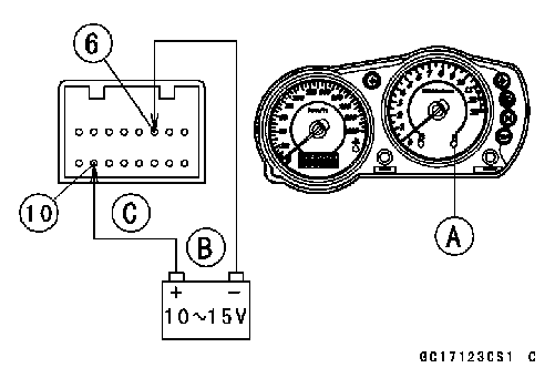
• Using two auxiliary leads, supply battery power to the FI indicator light (LED) [A]. 12 V Battery [B] FI Indicator Light (LED) Check Connector: Meter Connector [C] (disconnected) Connection: W/BK Lead Terminal [10] of the Meter → Battery (+) Terminal BR/R Lead Terminal [6] of the Meter → Battery (–) Terminal Criterion: The light (LED) should light.
1. ECU 2. Water-proof Joint C 3. Ignition Switch 4. Meter Unit 5. Ignition Fuse 10 A 6. Main Fuse 30 A 7. Battery 8. Frame Ground 9. Joint Connector
• Remove: Seat (see Seat Removal in the Frame chapter) Grab Rails [A] (see Seat Cover Removal in the Frame chapter) Center Seat Cover [B] (see Seat Cover Removal in the Frame chapter) Seat Covers [C] (see Seat Cover Removal in the Frame chapter) Rear Fender Rear Bolts [D]
• Take the ECU [B] out along with the harness. • Disconnect the ECU lead connectors.
• Fit [A] the bracket on the ECU as shown.
ECU Power Supply Inspection
with compressed air.
OFF, using a tester and needle adapter set. Battery [B] Tester [C]
|
||||
|
|
Последнее изменение этой страницы: 2016-08-10; просмотров: 398; Нарушение авторского права страницы; Мы поможем в написании вашей работы! infopedia.su Все материалы представленные на сайте исключительно с целью ознакомления читателями и не преследуют коммерческих целей или нарушение авторских прав. Обратная связь - 216.73.216.27 (0.007 с.) |

 If the reading is incorrect, check the following. Battery
 Oxygen Sensor Inspection
 • Remove the air switching valve hose from the fitting.
 • Next, remove the plugs from the fitting [A] with idling.
 • Remove the meter unit (see Meter Unit Removal in the Electrical System chapter).
 ECU Removal
 • Pull down the rear fender rear [A].
 • Remove the ECU bracket bolts [A].
 ECU Installation
 • Visually inspect the terminals [A] of the ECU connectors. If the connector is clogged with mud or dust, blow it off
 • With the ECU connectors [A] connected, check the fol- lowing ground lead for continuity with the ignition switch