Заглавная страница Избранные статьи Случайная статья Познавательные статьи Новые добавления Обратная связь КАТЕГОРИИ: ТОП 10 на сайте Приготовление дезинфицирующих растворов различной концентрацииТехника нижней прямой подачи мяча. Франко-прусская война (причины и последствия) Организация работы процедурного кабинета Смысловое и механическое запоминание, их место и роль в усвоении знаний Коммуникативные барьеры и пути их преодоления Обработка изделий медицинского назначения многократного применения Образцы текста публицистического стиля Четыре типа изменения баланса Задачи с ответами для Всероссийской олимпиады по праву 
Мы поможем в написании ваших работ! ЗНАЕТЕ ЛИ ВЫ?
Влияние общества на человека
Приготовление дезинфицирующих растворов различной концентрации Практические работы по географии для 6 класса Организация работы процедурного кабинета Изменения в неживой природе осенью Уборка процедурного кабинета Сольфеджио. Все правила по сольфеджио Балочные системы. Определение реакций опор и моментов защемления |
Modern Processes of Metal Production for Castings
The most common foundry metals are cast irons, steels, bronzes, brasses, aluminium, magnesium and titanium alloys. The structure of alloys in our country and abroad is shown in table 3.1
Table 3.1 - Structure of foundry alloys in various countries
Grey cast iron is considered to be the most frequently used cast engineering material. It has high foundry properties, low cost and low mechanical properties. Nodular (high-streagth) cast iron has the same chemical composition as grey cast iron, except small content of modifier The tendency of using the non-ferrous alloys, especially aluminium ones, instead steels and cast irons had development in many countries last years. The aluminium alloys have small mass density g=2.7 g/cm3 (steels have g=7.8 g/cm3) and high specific strength su/g. The replacement of steels and cast irons by the aluminium alloys gives a chance to machine’s mass decrease and improve its quality and efficiency. As we can see (table 3.1), Ukrainian machinery does not realize the possibility for improvement of its production quality by changing of the foundry alloys structure.
3.8.1. Cast Iron Production for Castings
Iron-carbon alloys where carbon content is higher than solubility in austenite, i.e. greater than 2.14 %, are called cast irons. Real cast irons have the composition: 2.2...4.5 % C, 0.5...3.5 % Si, 0.5...1.2 % Mn, 0.01...0.20 % S, 0.03...1.20 % P. The most important indices of quality for non-alloyed cast irons are the carbon state (the amount of combined carbon), shape of graphite inclusions and state of metal matrix. The following cast irons are distinguished: white, mottled, chilled, grey, malleable, nodular (or high-strength) ones. All carbon is chemically combined in white cast iron. Correspondingly, all carbon is in the form of graphite in ferritic cast iron. Amount of chemically combined carbon in grey pearlitic cast iron is equal to 0.8 %. Carbon, silicon, aluminium promote graphitization. Chromium, manganese, vanadium, titanium, sulphur prevent this process. A distinction is made between ferrite, pearlite and ferrite-pearlite structures. Up to the recent years the most commonly used furnace to melt grey cast iron is a cupola, where about 70 per cent of this alloy used to manufacture of castings is smelted. A cupola (Fig. 3.16) is a typical shaft furnace (like a blast furnace): its design comprises a vertical pipe (steel shell) 8 on columns 2. But unlike the blast furnace only metal remelting process takes place in the cupola. Cupola charge consists of: ~35 % foundry iron (ingots); -30 % cast iron scrap; -15 % steel scrap; -15 % coke (fuel); -5 % limestone CaCO3 (flux).
Fig. 3.16. Cupola: 1 – fundament; 2 – column; 3 – folding cover; 4 – bottom; 5 – air tuyere; 6 – ventilator; 7 – refractory lining; 8 – steel shell of shaft; 9 – cast iron plates; 10 – charging window; 11 – spark extinguish; 12 – pipe; 13 – charging bucket; 14 – taphole; 15 – receiver; 16 – slag taphole; 17 – cast iron taphole; 18 – ladle
The cupola has a refractory lining 7 inside and a window 10 for charging a furnace burden. Compressed air is given from compressor 6 through a pipe, wind box and tuyeres 5 into the cupola. Air is necessary for coke burning and high temperature (~1700°C) attainment. Metal charge is melted at high temperature. Besides that metal absorbs carbon and sulphur of coke. This is the main disadvantage of the cupola. From the cupola cast iron drains through an intermediate taphole 14 into a receiver 15, than through taphole 17 it is tapped into a ladle 18. When the cupola is without the receiver, cast iron fills up a hearth (lower part) of the cupola. To tap metal from the receiver, the tap hole is opened by picking up a bott. The slag is removed through the slag hole.
When melting process is finished the locking bar is displaced, bottom plates 3 are turned and rest of charge is withdrawn. Next, repair of the cupola lining is accomplished. The cupola is a furnace of permanent action but usually its working time ranges from - absorption of carbon by cast iron and difficulties in production of low-carbon cast iron (the less carbon content the higher mechanical properties); - molten cast iron absorbs sulphur which decreases properties of iron and is a reason of red (hot) shortness; - it is difficult to control and change chemical composition of cast iron; - it is difficult to overheat cast iron more than 1420...1430°C; - high content of CO (9...12 %), SO2 (1...2 %) and dust (20 g/m3) in waste gases and consequent ecological problems. For these reasons electrical furnaces, such as electric arc and induction units, are used to melt cast iron. To meet high demands of developed up-to-date technology the electric furnaces are the most satisfactory melting units, because: - coke, rich in sulphur, isn't consumed, providing therefore cast irons with less carbon and sulphur content and consequently high mechanical properties to be obtained; - electric furnaces give a possibility to overheat metal up to demanded temperature. Design and operation of electric-arc furnace were considered in part "Metallurgy". Figure 3.17 portrays crucible (coreless) induction furnace comprises the following principal units: metallic carcass, inductor 1, rammed crucible 2, axis of furnace tilting mechanism, lip, metal 3, electric generator (high-frequency) or transformer (main-frequency) switch board.
Fig. 3.17. Induction furnace: 1 – inductor; 2 – crucible; 3 – metal (charge)
The induction furnace operates as a transformer without an iron core, the primary winding of which is a multiturn coil-inductor 1 and the secondary winding and the load at the same time is the metal to be melted. The higher frequency the smaller pieces of charge may be heated and melted. For this reason small capacity furnaces with high frequency generator are used. But induction furnaces of high capacity (1...30 tons) are equipped with transformers and sometimes triple frequency multipliers (150 Hz). Piece of charge, not less than 250 mm in size may be melt in mains-frequency furnace. Cast iron melted in electric-arc and induction furnaces has higher mechanical and service properties than the one produced in the cupola. A charge in electric furnaces consists of steel and iron scrap, foundry iron, ferromanganese, ferrosilicon and other ferroalloys. When basic lining is used, sulphur and phosphorus may be removed from metal. Nodular Cast Iron Production. Nodular, or high-duty, or high-strength cast iron with spheroidal graphite has the same chemical composition as grey cast iron, except sulphur content, which is lower in nodular cast iron (0.8...0.12 % S in grey cast iron and 0.01...0.02 % S in nodular one). Unlike grey cast iron, which has lamellar graphite, nodular cast iron contains spheroidal graphite and, due to this reason, has higher mechanical properties. To convert lamellar graphite in spheroidal foundrymen carry out inoculation procedure, i.e. they add inoculator (magnesium, cerium, lanthanum, yttrium) in liquid cast iron. Inoculator reacts with sulphur in metal:
So, low sulphur content ensures obtaining of spheroidal graphite. That is why metal for nodular cast iron is melted in induction or electric-arc furnaces to prevent its saturation with sulphur. Nodular cast iron has ferrite or pearlite, or ferrite-pearlite metal matrix structure and globular graphite inclusions. In case of heat-treatment martensite, troostite, or sorbite structure may be received. Malleable cast iron is produced by annealing of white cast iron. The less amount of carbon and silicon in iron, the more easily the white cast iron may be produced. Therefore liquid metal contains 2.2...2.9 % C and 0.8...1.4 % Si. Thickness of casting should not exceed 50...60 mm. It is very difficult to receive low carbon content in cupola cast iron, because coke saturates liquid metal with carbon. Thus, induction and electric-arc furnaces are used to smelt metal in malleable cast iron production. Sometimes duplex- process (cupola and electric-arc furnace) is used. Cast iron from the cupola is poured into arc furnace, where it is overheated. The carbon content in it is lowered by steel scrap additions in the furnace. Malleable cast iron possesses intermediate foundry properties between grey cast iron and carbon steel. Castings are normally manufactured with risers. Sand, metallic, shell and centrifugal moulds may be employed for iron casting.
3.8.2. Steel Castings Production
Cast steels are divided into carbon and alloy steels. The grade of cast steel is marked by the letter Л (cast): - carbon steels: 40Л, 35Л, 25Л; - alloy steels: 30X2HBЛ. Unlike cast iron steel has worse foundry properties: high melting point (~1500°C), high shrinkage (el»1.5...2.5 %, ev»5...8 %). But steel is distinguished by its high mechanical properties: su = 500...2500 MPa, d up to 30%, j up to 50 %. Steel castings are usually supplied with risers. They are intended to produce parts designed for operation in severe service conditions. The electric-arc furnaces and, sometimes, induction coreless high-frequency furnaces are used to melt steel for castings. Sulphur and phosphorus may be removed from steel in basic electric-arc furnaces. Induction furnaces are used as remelting units only. Sand, investment, shell and, sometimes, metal moulds may be used.
3.8.3. Melting of Copper-Base Alloys
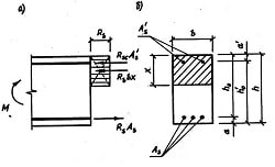
Two types of copper-base alloys are mainly employed: - brasses, alloys of copper with zinc and other elements (Al, Fe, Mn, Pb, Si); - bronzes, alloys of copper with tin and other elements (Ni, Sn, Pb, Zn, Al, Si, Mn, Be), among which there may be zinc, but only in combination with other elements and in small quantities. Copper-base alloys have good wear and corrosion resistance in atmosphere, fresh and sea water, and other aggressive media. Melting point of copper alloys is about 1100°C, pouring temperature is about 1200°C. They have relatively good casting properties: high fluidity, medium shrinkage (el=1.4...1.7 %, up to 2.5 %, only for some alloys). Furnaces of different types and design are used to melt copper-base alloys. Flame furnaces as well as electrical-both arc and induction furnaces are most frequently used for this purpose. In small scale foundries crucible furnaces are mainly employed. Many elements, such as Zn, Si, Al and others, are easily oxidized. Some of them even evaporate. What is more, some elements comprising copper-base alloys in liquid state tend to gas absorption from the furnace atmosphere, especially hydrogen. Thus, melting furnaces should provide the possibility of rapid melting with minimum losses of easy-oxidizing and evaporating components as well as of protecting metal against hydrogen saturation. To protect metal against oxidizing and hydrogen saturation, melting of copper-base alloys is done under fluxes, comprising charcoal, chlorides, fluorides, soda glass and other components. Reverberatory furnaces may be stationary or tilting (Fig. 3.18) and are used in those cases when it is necessary to produce a great amount of metal. This type of furnaces is mostly oil- or gas-fired. In reverberatory furnace metal and slag are melted due to direct contact with gases and heat from the roof and walls radiated downward on the charge. The furnace (in our case the tilting one) is burned by jet 1, which is supplied by oil or gas. Combustion gases pass through a combustion chamber 2, melting chamber 3 and tapping throat 4 into exhaust pipe. Contact of large metal surface with furnace gases is a major disadvantage of these furnaces, as it facilitates metal saturation with gases and causes high metal losses.
Fig. 3.18. Tilting reverberatory furnace: 1 – yet; 2 – combustion chamber; 3 – melting chamber; 4 – tapping throat; 5 – slag; 6 – metal
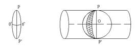
Electrical arc furnaces of indirect heating (Fig. 3.19) are the mostly used furnaces to melt copper-base alloys. Electrical arc is formed between two horizontal electrodes 1 and is located at a certain distance from the metal surface. Metal heating takes place on the account of the heat radiation from electrical arc and red-hot lining surface. Disadvantages of the arc furnaces are noise, caused by the electric arc; high temperature of electric arc (~3000°C), which facilitates metal burning, its evaporating and quick wear of lining. Induction furnaces are divided into coreless high and mains-frequency and mains- frequency with steel core. A furnace with the steel core 1 (Fig. 3.20) represents as if step-down transformer where metal in the furnace is a secondary winding.
Fig. 3.19. Electric arc furnace of indirect heating a – drawing; b - scheme: 1 – electrode;
2 – electric arc; 3 – tilting mechanism
Fig. 3.20. Induction furnace with the steel core: 1 – steel core; 2 – metal channel
Transformation of electrical energy into thermal one in these furnaces is performed in the following way. Mains-frequency current in a primary winding causes a magnetic flux around it closing through a steel core of the transformer and inducing secondary current in the metal present in a ring-like channel 2. Metal in the channel is melted, preheated, moves around core 1 and heats the metal into crucible. So we have metal circulation in the furnace. Peculiarity of melting in induction furnaces with the steel core lies in the following: liquid metal filling bottom ducts should remain in the furnace after tapping to form a closed electrical circuit during the next heat. Due to this reason it is difficult to pass over from one alloy grade to another. Crucible furnaces are used for melting small amounts of certain foundry alloys. Crucible furnaces may be either stationary or rotary. They are fired by liquid, gaseous or solid fuel. Figure 3.21 represents a crucible furnace.
Fig. 3.21. Crucible furnace: 1 – crucible; 2 – furnace; 3 – hole for flame jet
Deoxidation and Refining of Copper -Base Alloys. The charge melting in the furnace reacts with furnace atmosphere, lining and fluxes. As a result, some elements and their compounds transfer to molten metal, slag and gaseous atmosphere. Presence of soluble and nonsoluble oxides in metal causes decrease in physical and mechanical properties and formation of defects in castings (gas porosity, slag holes, etc.). To improve quality of castings deoxidation of alloys is performed. Deoxidizers for copper-base alloys are divided into 2 groups: - surface-active and non-soluble in metal; - soluble in liquid metal and active inside the alloy. Surface-active deoxidizers are calcium carbide (CaC2), magnesium boride (Mg3B2), carbon (C) and liquid boric slag. They are milled and given on the surface of metal:
The most commonly soluble deoxidizer of Cu-base alloys is phosphorous consumed in the form of foundry alloy (~10 % P, 90 % Cu):
Refining is a process of cleaning of liquid alloy from hard oxides, slag particles and gases. More efficient refining process is flotation (Fig. 3.22). It consists of blowing neutral gases (N2, Ar) through the liquid alloy or introducing different substances into it in oredr to obtain as a result products of gaseous or vaporous nature (e. g. P2O5). Gas or vapor bubbles floating up to the metal surface carry away non-metallic inclusions and penetrating inside bubbles gases (H2). Sand, metal, investment, shell and centrifugal moulds are employed.
Fig. 3.22. Flotation refining process
3.8.4. Melting of Aluminum-Base Alloys
Aluminum-base alloys possess high fluidity, comparatively low shrinkage (e1»1%), low tendency to form hot cracks and porosity, and low melting point (~650°C). Al-alloys have good mechanical properties, high corrosion resistance and low density (2.7 g/cm3). The most widely used alloys are Al-Si (6...22 % Si), Al-Cu (3.6...6.0 % Cu), Al-Mg (9.5...11.5 % Mg), Al-Si-Cu, Al-Si-Cu-Mg and others alloys. Inoculants, such as Ti, Zr, B and V (0.05...0.15 %) are added to the alloys to refine grains and consequently, to improve mechanical properties. Different furnaces are used to prepare Al-base alloys. In small-scale foundries they are crucible (stationary and tilting) furnaces with solid, liquid fuels or gas-fired. In large-scale foundries stationary flame furnaces as well as electric resistance and induction furnaces are used. Design of furnaces for melting Al-base alloys is the same as for Cu-base alloys. But in crucible and induction furnaces crucibles are made of cast iron or graphite-chamotte mixture. Working surface of cast iron crusibles is painted to prevent dilution (paint: chalk, zinc oxide, water glass, water). Figure 3.23 represents a reverberatory electrical resistance-tilting furnace for melting Al-alloys.
Fig. 3.23. Reverberatory electrical resistance furnace: 1 – charging window; 2 – bath; 3 – heating elements
The following techniques of Al-alloys treatment in addition to special measures for preparation of the furnaces, charge and melt under coating effluxes are applied: - degassing for the purpose of gas removal from the alloy; - inoculation to get fine grain structure with improved mechanical properties. Degassing is carried out by chlorine, which forms aluminum chloride. Bubbles of aluminum chloride carry away the hydrogen, the nitrogen and oxides from metal (Fig.3.24).
Fig. 3.24. Principle of degassing
After degassing inoculation treatment is carried out by adding inoculants in liquid Al-alloys or by keeping liquid metal under inoculating mixes consisting of fluorides and chlorides (CaF2, MnCl2, NaCl, ZnCl2, etc.):
where AlCl3 is refining gas, Na is inoculant.
Metallic, sand (intricate castings), pressure-die and centrifugal moulds are used for Al-base alloys pouring.
3.8.5. Melting of Magnesium-Base Alloys
Magnesium is an element of high chemical activity. It reacts with oxygen, in liquid state very easy catches fire and absorbs hydrogen and nitrogen. Magnesium has good foundry properties like high fluidity, small shrinkage (e1= 1.1...1.4 %) and low melting point (651°C). Pouring temperature of Mg-base alloys ranges from 650 to 700 °C. Cast alloys are alloyed with Al, Zn, Mn, Zr and other elements. By low density (1.7 g/cm3) they are used in automobile engineering, aircrafts, rockets, etc. Due to high chemical activity magnesium-base alloys are melted in crucible induction and electric resistance furnaces under slag coating, consisting of chlorides of Mg, K and Na. During pouring magnesium may catch fire. To prevent this, magnesium stream is powdered by sulphur. Sulphur is burned and gas SO2 prevents the reaction between magnesium and oxygen. Sulphur and boric acid are added in moulding mixes to prevent burning of magnesium within a mould. Metallic, pressure-die and sand moulds are normally used.
3.8.6. Melting of Titanium-base Alloys
Titanium possesses high melting point equal to 1665°C. In liquid state it reacts with O2, N2, H2 very intensively. Melting and pouring of Ti-alloys is carried out in vacuum induction furnaces (Fig. 3.25). When melting process is completed the chamber is turned and liquid metal is poured into the mould.
Fig. 3.25. Melting of titanium-base alloys in vacuum: 1 – liquid metal; 2 crucible; 3 – manipulator; 4 - vacuum chamber; 5 - mould; 6 - inductor
METAL FORMING Metal forming, or plastic metal working, is based on an ability of metals to get residual plastic deformation by affecting of external forces on a half-finished part. Main advantages of the process are: - improvement of structure, density, physical and mechanical properties of metals and alloys; - reducing of metal outlay as compared with cutting (increasing of metal utilization coefficient); - high labor productivity. Approximately 90 % of steel and 55 % of non-ferrous metals undergo metal forming operations. On the base of metal forming new kinds of heat-mechanical (thermomechanical) treatment have been recently found out. These methods are known to be combination of metal forming and heat-treatment and provide regulation of structure, peening (strain hardening) degree and mechanical properties.
|
||||||||||||||||||||||||||
|
|
Последнее изменение этой страницы: 2021-12-15; просмотров: 134; Нарушение авторского права страницы; Мы поможем в написании вашей работы! infopedia.su Все материалы представленные на сайте исключительно с целью ознакомления читателями и не преследуют коммерческих целей или нарушение авторских прав. Обратная связь - 3.15.179.9 (0.075 с.) |


 (3.3)
(3.3)


 (3.4)
(3.4) (3.5)
(3.5) (3.6)
(3.6) (3.7)
(3.7)


 (3.8)
(3.8)