Заглавная страница Избранные статьи Случайная статья Познавательные статьи Новые добавления Обратная связь КАТЕГОРИИ: ТОП 10 на сайте Приготовление дезинфицирующих растворов различной концентрацииТехника нижней прямой подачи мяча. Франко-прусская война (причины и последствия) Организация работы процедурного кабинета Смысловое и механическое запоминание, их место и роль в усвоении знаний Коммуникативные барьеры и пути их преодоления Обработка изделий медицинского назначения многократного применения Образцы текста публицистического стиля Четыре типа изменения баланса Задачи с ответами для Всероссийской олимпиады по праву 
Мы поможем в написании ваших работ! ЗНАЕТЕ ЛИ ВЫ?
Влияние общества на человека
Приготовление дезинфицирующих растворов различной концентрации Практические работы по географии для 6 класса Организация работы процедурного кабинета Изменения в неживой природе осенью Уборка процедурного кабинета Сольфеджио. Все правила по сольфеджио Балочные системы. Определение реакций опор и моментов защемления |
Connection: Pink/white – Pink/white
[1]
P/W
[1]
P/W
P/W
4-22 PGM-FI SYSTEM
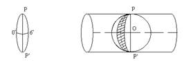
DTC 21 (O2 SENSOR)
Before starting the inspection, check for loose or poor contact on the O2 sensor 1P (Black) connector or O2 sensor cap and recheck the MIL blinking.
ECM
O2 SENSOR
Bl Bl/W
Probable cause • Open or short circuit in Black/white or Black wire between the O2 sensor and ECM
• Faulty O2 sensor • Faulty ECM
DTC 21-1 (O2 Sensor)
O2 Sensor System Inspection Start the engine and warm up the engine up to coolant temperature is 80°C (176°F). Test-ride the motorcycle and check the O2 sensor with the HDS pocket tester.
Is the DTC 21-1 indicated?
4-23 PGM-FI SYSTEM
O2 Sensor Inspection Replace the O2 sensor with a known good one (page 4-47). Connect the ECM 33P (Black) connector.
Start the engine and warm up the engine up to coolant temperature is 80°C (176°C). Test-ride the motorcycle and recheck the O2 sensor with the HDS pocket tester. Is the DTC 21-1 indicated?
YES – Replace the ECM with a known good one and recheck.
NO – Faulty original O2sensor
DTC 29 (IACV)
Before starting the inspection, check for loose or poor contact on the IACV 4P (Black) connector and recheck the MIL blinking.
ECM
IACV
Bu/W
Bu/Bl
Br/W
Br/Bl
Probable cause • Open or short circuit in wires (Blue/white, Blue/black, Brown/white, Brown/black) between the IACV and ECM
• Faulty IACV • Faulty ECM
4-24 PGM-FI SYSTEM
Recheck DTC Erase the DTC’s (page 4-5). Turn the ignition switch ON and engine stop switch "
Check the IACV with the HDS pocket tester.
Is the DTC 29-1 indicated?
YES – GO TO STEP 2.
NO – • Intermittent failure
• Loose or poor contact on the IACV 4P (Black) connector
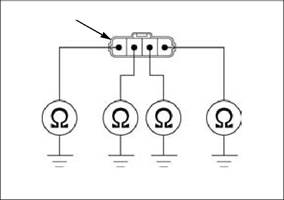
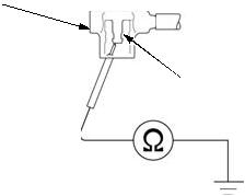
IACV Short Circuit Inspection Disconnect the ECM 33P (Black) connector (page 4-50). Check for continuity between the IACV 4P (Black) connector [1] of the wire side and ground. Connection: Blue/white – Ground Brown/white – Ground Brown/black – Ground Blue/black – Ground Is there continuity? YES – • Short circuit in Blue/white or Brown/white wire • Short circuit in Brown/black or Blue/ black wire
NO – GO TO STEP 3.
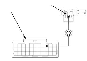
IACV Open Circuit Inspection Check for continuity between the ECM 33P (Black) connector [1] and IACV 4P (Black) connector [2] of the wire side. Connection: Brown/white – Brown/white Blue/white – Blue/white Brown/black – Brown/black Blue/black – Blue/black
• Open circuit in Brown/black or Blue/ black wire
[1]
Bu/W Br/W Br/Bl Bu/Bl
Br/Bl
Bu/Bl
[1]
4-25 PGM-FI SYSTEM
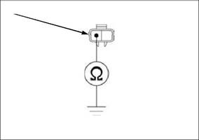
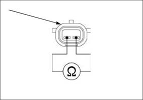
IACV Resistance Inspection Turn the ignition switch OFF. Disconnect the IACV 4P (Black) connector [1] (page 7-15). Measure the resistance at the IACV side connector. Connection: A (Blue/black) – D (Blue/white) B (Brown/black) – C (Brown/white) Standard: 110 – 150 Ω (25°C/77°F)
Is the resistance within 110 – 150 Ω (25°C/77°F)?
DTC 33-2 (EEPROM)
Recheck DTC Erase the DTC’s (page 4-5). Turn the ignition switch ON and engine stop switch " Recheck the ECM EEPROM.
Is the DTC 33-2 indicated?
YES – Replace the ECM with a known good oneand recheck.
NO – Intermittent failure
A D
B C
DTC 54 (BANK ANGLE SENSOR)
Before starting the inspection, check for loose or poor contact on the bank angle sensor 2P connector and recheck the MIL blinking.
ECM
From ENGINE
STOP SWITCH
Bl/Bu
R/Bu
BANK ANGLE SENSOR
Probable cause
• Open circuit in Black/blue wire between the engine stop switch and bank angle sensor • Open or short circuit in Red/blue wire between the bank angle sensor and ECM
• Faulty bank angle sensor • Faulty ECM
4-26 PGM-FI SYSTEM
|
||||||||||||||||||||||||||||||||||||||||||||||||||||||||||||||||||||||||||||||||||||||||||||||||||||||||||||||||||||||||||||||||||||||||||||||||||||||||||||||||||||||||||||||||||||||||||||||||||||||||||||||||||||||||||||||||||||||||||||||||||||||||||||||||||||||||||||||||||||||||||||||||||||||||||||||||||||
|
|
Последнее изменение этой страницы: 2016-04-08; просмотров: 316; Нарушение авторского права страницы; Мы поможем в написании вашей работы! infopedia.su Все материалы представленные на сайте исключительно с целью ознакомления читателями и не преследуют коммерческих целей или нарушение авторских прав. Обратная связь - 3.129.45.92 (0.037 с.) |


 ".
".