Заглавная страница Избранные статьи Случайная статья Познавательные статьи Новые добавления Обратная связь КАТЕГОРИИ: ТОП 10 на сайте Приготовление дезинфицирующих растворов различной концентрацииТехника нижней прямой подачи мяча. Франко-прусская война (причины и последствия) Организация работы процедурного кабинета Смысловое и механическое запоминание, их место и роль в усвоении знаний Коммуникативные барьеры и пути их преодоления Обработка изделий медицинского назначения многократного применения Образцы текста публицистического стиля Четыре типа изменения баланса Задачи с ответами для Всероссийской олимпиады по праву 
Мы поможем в написании ваших работ! ЗНАЕТЕ ЛИ ВЫ?
Влияние общества на человека
Приготовление дезинфицирующих растворов различной концентрации Практические работы по географии для 6 класса Организация работы процедурного кабинета Изменения в неживой природе осенью Уборка процедурного кабинета Сольфеджио. Все правила по сольфеджио Балочные системы. Определение реакций опор и моментов защемления |
Nanjing Fire Protection Technology Co., Ltd.Стр 1 из 3Следующая ⇒
Nanjing Fire Protection Technology Co., Ltd.
Content
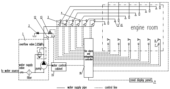
2.System structure ЎЎЎЎЎЎЎЎЎЎЎЎЎЎЎЎЎЎЎЎЎЎ 3.Key parameters in systemЎЎЎЎЎЎЎЎЎЎЎЎЎЎЎЎЎЎ 4.System control mode and operation flowЎЎЎЎЎЎЎЎЎЎЎ 5.Critical piecesЎЎЎЎЎЎЎЎЎЎЎЎЎЎЎЎЎЎЎЎЎЎ 5.1 Selector valveЎЎЎЎЎЎЎЎЎЎЎЎЎЎЎЎЎЎЎЎЎ 5.2 XYK2/150 self locking pressure switchЎЎЎЎЎЎЎЎЎЎЎ 5.3 ZSXTC nozzleЎЎЎЎЎЎЎЎЎЎЎЎЎЎЎЎЎЎЎЎЎ 5.4 Water supply pumpЎЎЎЎЎЎЎЎЎЎЎЎЎЎЎЎЎЎЎ 5.5 Fire alarm and extinguishing controllerЎЎЎЎЎЎЎЎЎЎ 5.6 Solenoid overflow valveЎЎЎЎЎЎЎЎЎЎЎЎЎЎЎЎЎ 5.7 By pass valveЎЎЎЎЎЎЎЎЎЎЎЎЎЎЎЎЎЎЎЎЎ 6.System operation flowЎЎЎЎЎЎЎЎЎЎЎЎЎЎЎЎЎЎЎЎ 7.Installations and debuggingЎЎЎЎЎЎЎЎЎЎЎЎЎЎЎЎЎЎ 8.Maintenance ЎЎЎЎЎЎЎЎЎЎЎЎЎЎЎЎЎЎЎЎЎЎЎ 2007.3 Overview The Marine Medium Pressure Water Mist Fire Extinguishing System is applicable to the place where set the A type machine in the new or renewed ship, such as the ships diesel engine in the engine room, diesel generator, fuel boiler, incinerator, fuel device etc. This system has no pollution, being harmless to human being and high extinguishing property. As the Green Fire Extinguishing System, it meets the environmental protection requirements and will bring benefit to mankind definitely. System Structure System schematic The combined distribution system is to protect several areas by a set of fire-distinguishing device. The design quantity should meet the need of the largest protected zone. This is the system schematic:
Device schematic
System control mode and operation flow
System control mode There is three control methods: automatic, electric-manual and mechanical mergency manual control. 4.1.1 Automatic control: Set the fire alarm and extinguishing controller and water pump control cabinet in Ў°AutoЎ± mode, the system will be in automatic control state. When there is a fire, fire detector will send fire signal to fire alarm and extinguishing controller. Then fire alarm and extinguishing controller give off audible and visible signals as well as extinguishing command to open corresponding selector valve and pump set, the water mist will be discharged into protected zone. After extinguishing, press the reset button on fire alarm and extinguishing controller to close selector valve and water pump set, also press reset button of pressure switch to reset the system to servo state. 4.1.2 Electric-manual control: When fire is observed, press the corresponding start button on fire alarm and extinguishing controller or corresponding manual alarm button, the system will start and discharge water mist. After extinguishing, reset the manual alarm button or the reset button on fire alarm and extinguishing controller to close selector valve and pump set. Rest the pressure switch manually to reset the system to servo state. System operation flow
5 CRITICAL PIECES Selector valve 5.1.1 Structure ЈЁas follow diagramЈ©
Key technical parameters
Instruction Selector valve is mainly used in combined distribution system to control the agent flow direction and make sure that the agent be sprayed into fire protected area. It is installed on the distribution pipe with its outlet connecting to delivery pipe. Selector valve is normal close, can be started electrically and manually. Electrical start ЈєWhen a fire appears, the fire alarm and extinguishing controller will send DC24V active signal to open the selector valve, then the agent flows into the protected area via the selector valve. Manual startЈє Turn the start handle clockwise (or anticlockwise) by special tool to limiting position to open the selector valve The selector valve can reset automatically when power off if it is stated electrically. For manual open, turn the start handle to the position of Ў°№ШЈЁOFFЈ©Ў± to reset it manually
XYK2/150 pressure switch 5.2.1 Structure: 5.2.2 Key parameters:
Instruction The pressure switch is fixed behind selector valve. It operates when the system releases agent and then send feedback signal to fire alarm and extinguishing controller, showing the agent has been released into certain protected area. Check and reset it manually for later use after operation. ZSXTC nozzle 5.3.1 Structure:
5.3.2 Key parameters:
Water supply pump Overview High pressure plunger pump with safety overflow valve, buffer and filter, etc. Instruction There are inlets and outlets on both sides for installation. Foundation footing must be strong and big enough to make sure that the device will not go down, bend and distort after installation. Besides, the foundation should be horizontal to avoid device declining. Direction sign on the pump is to show the rotation direction. The pressure in inlet should be net positive. Do not start pump when there is no water in it. More details refer to Instruction Manual. Solenoid overflow valve Overview Because the water flow is different among protected zones (quantity of nozzles is different), and the flow of pump is chose according to the maximum zone, a solenoid overflow valve will be needed to ensure that the pump can be start without shake. Key technical parameters
Instruction The solenoid overflow valve is fixed on side of safety valve with a joint on its outlet. The joint should be designed according to project, do not alter it at will. It is normal close, should open and close in step with the selector valve in the same zone.
By pass valve Overview By pass valve is an important part in water mist fire extinguishing system, it insure the pump runs noload when start and stop. Key technical parameters
Instruction The solenoid overflow valve is fixed on one side of safety valve, and controlled by water pump control cabinet. When the water pump starts or stops, the by pass valve opens for 4~6s, then closes.
System operation flow 6.1 Operator should read this Instruction Manual as well as Instruction Manuals of plunger pump, water pump control cabinet and fire alarm and extinguishing controller. And be familiar with relative drawing or documents. 6.2 The integrative fire alarm system consists of this system and the fire alarm and extinguishing system. It has three control modes: automatic control, electric-manual control and manual emergency control. 6.3 Set the fire alarm and extinguishing controller in Ў°automaticЎ± control mode usually, and switch the Ў°manual/automaticЎ± selector switch on water pump cabinet to Ў°automatic Ў±position. Then the system is in auto state. Usually the system is in this state. When there is a fire, fire detector will send fire signal to fire alarm and extinguishing controller, the later will give off audible and visible alarm signal as well as send extinguishing command to start corresponding selector and pump set to spray water mist. After extinguishing, press the reset button on fire alarm and extinguishing controller to stop spraying. 6.4 If the fire is observed, do as follows: Press the manual alarm button or the corresponding start button on fire alarm and extinguishing controller to start system. 6.5 If the electric control cannot start system, operation procedure of emergency start is: Open the corresponding selector valve manually, and switch the selector switch (on water pump control cabinet)Ў±manual/automaticЎ± to Ў°manualЎ± position, then press the start button on water pump control cabinet, the pump will be started and then start the system. 6.6 After extinguishing, reset the system in time. The operation flow is as follows: a) If the system is started automatically or electric-manually, press the reset button on fire alarm and extinguishing controller to shutdown water pump and close selector valve, then press reset button of pressure switch. b) For emergency start, press the stop button on water pump control cabinet, reset the selector valve and pressure switch manually. INSTALLATIONS and debugging Installation 7.1.1 General rules 7.1.1.1 The installation of the water mist fire extinguishing system should be comply with the design drawings and relative technical documents. It can be not altered without agrees of design company. 7.1.1.2 Make construction notes during the installation. 7.1.1.3 Installation place temperature: ЎЭ4ЎжЈЎЬ50Ўж. 7.1.1.4 The place should have special power supply (three phase three wire system): AC380V/50Hz or AC440V/60Hz. 7.1.1.5 The place should be easy for in and out, and not easy for fire occurring. 7.1.1.6 No explosive or electric dust, and corrosive substance in the air, or else it should have prevention measure. 7.1.2 Pump installation 7.1.2.1 Model and size should be comply with design requirements. And it should has CCS certificate, quality certificate and installation instruction. 7.1.2.2 Water tank and pump set inlet should be connected with flexible connecting pipe, make sure that the water inlet pressure is net positive. 7.1.2.3 No air cell and air leak on suction pipe of water pump.
7.1.2.4 Others refer to Instruction Manual for pump. 7.1.3 Fix the distributing pipe on the frame firmly. 7.1.4 Selector valve installation 7.1.4.1 Install the selector valve on side of operation surface with height no more than 1.7m and no less than 1.4m. 7.1.4.2 Stamp protected area name or serial number on selector valve. 7.1.5 Pipe installation 7.1.5.1 The material of pipes and the pipefitting are stainless steel. 7.1.5.2 Connecting type is threaded connection. Wind male screw with sealing tape. 7.1.5.3 Pipe cradle installation: a) Fix the pipeline firmly. The maximum space between cradles is as table 7.1.5.3 b) Fix the end of the pipeline with cradle. The length of the pipeline between the cradle and nozzle should be no more than 250mm. The maximum space between Table 7.1.5.3
7.1.6 Tube tests 7.1.6.1 The pipe should undergo hydraulic test after installation. 7.1.6.2 Hydraulic test pressure is 5.25MPa, dwell time is 5min, the connection should have no leakage, and pipe should be no distortion. 7.1.6.3 Blow and sweep the pipe with compressed air or N2 after finishing these tests. The velocity no less than 20m/s. Use calico to check if there are any rust, dust, stain and other dunghill. 7.1.7 Nozzle installation 7.1.7.1 Nozzle should be installed after test and air lancing. 7.1.7.2 Check the nozzleЎЇs model and size one by one. 7.1.7.3 Do not demount and alter nozzles when installation. Any ornamental coat is forbidden. 7.1.8 As to fire alarm and extinguish controller, refer to its installation instructions. System debugging 7.2.1 General rules 7.2.1.1 Debug the system after installation. 7.2.1.2 The system should be debugged by professional with specific functions. 7.2.2Debugging 7.2.2.1 Debugging of fire alarm and extinguishing device refer to its Debugging Instruction. 7.2.2.2 Test the system at least in two protected areas. 7.2.2.2.1 The test control mode should be automatic control or electric-manual control. 7.2.2.2.2 Cover the nozzles or protected objects with transparent plastic material as well as collect sprayed water. 7.2.2.2.3 Spray test should be last for 0.5min.Test results should meet following requirements: a) All the components of the system should work normally, every nozzle can spray water mist, and the press gauge shows right. b) Audible and visible alarm signal is right. c) The devices and the tubes should have no shake and mechanical damage. 7.2.2.2.4 After the tests, reset the system to normal state. Maintenance 8.1 Set a control, check and maintenance system for the system, special person is needed to take charge the system and keep it in a good condition. 8.2 The maintenance personnel must acquaint with its construction principle, performance and maintenance instruction. 8.3 Regular inspection and test for fire alarm and extinguishing control device. 8.3.1 Check its functions every day. 8.3.2 Check and test the following functions quarterly: 1. Audible and visible alarm; 2. Play charge and discharge test 1~2 times. Automatic switch test between main power supply and emergency power supply 1~3 times; 3. Test the alarm and signal display function of pressure switch; 4. Check the controlled display functions of pump and selector valve. 8.3.3 More information refers to its Maintenance Manual. 8.4 Regular inspection and test for pump 8.4.1 To start it manually per month. 8.4.2 To start it electrically quarterly. The operation time be more than 1min. Open the water test valve when running and close it after stop running. 8.4.3 Pump maintenance refers to its Maintenance Manual. 8.5 Check the water level in water tank per month. 8.6 Check the nozzle per month, clear away foreign matter in time. 8.7 Do operating test each year. 8.7.1 The test control mode should be automatic control or electric-manual control. 8.7.2 Cover the nozzles or protected objects with transparent plastic material as well as collect sprayed water. 8.7.3 Spray test should be last for 0.5min.Test results should meet following requirements: a) All the components of the system should work normally, every nozzle can spray water mist, and the press gauge shows right.
b) Audible and visible alarm signal is right. c) The devices and the tubes should have no shake and mechanical damage. 8.8 Debug trouble in time to make sure that the whole system can operate normally. 8.9 After every operation (including extinguishing and test), reset the system according to item 6.6. 8.10 After every operation (include extinguishing and test), clean or change filter gauze. 8.11 Make detail record after every test and maintenance. 8.12 Do not touch any component at will to avoid accident.
Nanjing Fire Protection Technology Co., Ltd.
Content
2.System structure ЎЎЎЎЎЎЎЎЎЎЎЎЎЎЎЎЎЎЎЎЎЎ 3.Key parameters in systemЎЎЎЎЎЎЎЎЎЎЎЎЎЎЎЎЎЎ 4.System control mode and operation flowЎЎЎЎЎЎЎЎЎЎЎ 5.Critical piecesЎЎЎЎЎЎЎЎЎЎЎЎЎЎЎЎЎЎЎЎЎЎ 5.1 Selector valveЎЎЎЎЎЎЎЎЎЎЎЎЎЎЎЎЎЎЎЎЎ 5.2 XYK2/150 self locking pressure switchЎЎЎЎЎЎЎЎЎЎЎ 5.3 ZSXTC nozzleЎЎЎЎЎЎЎЎЎЎЎЎЎЎЎЎЎЎЎЎЎ 5.4 Water supply pumpЎЎЎЎЎЎЎЎЎЎЎЎЎЎЎЎЎЎЎ 5.5 Fire alarm and extinguishing controllerЎЎЎЎЎЎЎЎЎЎ 5.6 Solenoid overflow valveЎЎЎЎЎЎЎЎЎЎЎЎЎЎЎЎЎ 5.7 By pass valveЎЎЎЎЎЎЎЎЎЎЎЎЎЎЎЎЎЎЎЎЎ 6.System operation flowЎЎЎЎЎЎЎЎЎЎЎЎЎЎЎЎЎЎЎЎ 7.Installations and debuggingЎЎЎЎЎЎЎЎЎЎЎЎЎЎЎЎЎЎ 8.Maintenance ЎЎЎЎЎЎЎЎЎЎЎЎЎЎЎЎЎЎЎЎЎЎЎ 2007.3 Overview The Marine Medium Pressure Water Mist Fire Extinguishing System is applicable to the place where set the A type machine in the new or renewed ship, such as the ships diesel engine in the engine room, diesel generator, fuel boiler, incinerator, fuel device etc. This system has no pollution, being harmless to human being and high extinguishing property. As the Green Fire Extinguishing System, it meets the environmental protection requirements and will bring benefit to mankind definitely. System Structure System schematic The combined distribution system is to protect several areas by a set of fire-distinguishing device. The design quantity should meet the need of the largest protected zone. This is the system schematic:
Device schematic
|
||||||||||||||||||||||||||||||||||||||||||||||||||||||||||||||||||||||||||||||||||||||||||||||||||||||||||||||||||||||||||||||||||||||||||||||||||||||||||||||||||||||||||||||||||||||||||||||||||||||||||||||||||||||||||||||||||||||||||||||||||||||||||||||||||||||
|
|
Последнее изменение этой страницы: 2017-02-05; просмотров: 399; Нарушение авторского права страницы; Мы поможем в написании вашей работы! infopedia.su Все материалы представленные на сайте исключительно с целью ознакомления читателями и не преследуют коммерческих целей или нарушение авторских прав. Обратная связь - 18.222.184.162 (0.104 с.) |
 Critical piece and their functions:
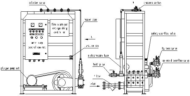 3 KEY parameters in system